Transcription of 12×12 DOTS MATRIX LED DRIVER WITH …
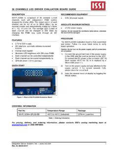
1 IS31FL3737 Integrated Silicon Solution, Inc. 1 Rev. A, 07/19/2016 12 12 DOTS MATRIX LED DRIVER with INDIVIDUAL auto breath FUNCTION July 2016 GENERAL DESCRIPTION The IS31FL3737 is a general purpose 12 12 LEDs MATRIX DRIVER with 1/12 cycle rate. The device can be programmed via an I2C compatible interface. Each LED can be dimmed individually with 8-bit PWM data which allowing 256 steps of linear dimming. IS31FL3737 features 3 auto Breathing Modes which are noted as ABM-1, ABM-2 and ABM-3. For each auto Breathing Mode, there are 4 timing characters which include current rising / holding / falling / off time and 3 loop characters which include Loop-Beginning / Loop-Ending / Loop-Times.
2 Every LED can be configured to be any auto Breathing Mode or No-Breathing Mode individually. Additionally each LED open and short state can be detected, IS31FL3737 store the open or short information in Open-Short Registers. The Open-Short Registers allowing MCU to read out via I2C compatible interface. Inform MCU whether there are LEDs open or short and the locations of open or short LEDs. The IS31FL3737 operates from to and features a very low shutdown and operational current. IS31FL3737 is available in QFN-40 (5mm 5mm) package. It operates from to over the temperature range of -40 C to +125 C.
3 FEATURES Supply voltage range: to 12 current source outputs for row control 12 switch current inputs for column scan control Up to 144 LEDs (12 12) in dot MATRIX Programmable 12 12 (48 RGBs) MATRIX size with de-ghost function 1 MHz I2C-compatible interface Selectable 3 auto breath Modes for each dot auto breath Loop Features interrupt pin inform MCU auto breath Loop completed auto breath offers 128 steps gamma current, interrupt and state look up registers 256 steps Global Current Setting Individual on/off control Individual 256 PWM control steps Individual auto breath Mode select Individual open and short error detect function Cascade for synchronization of chips QFN-40 (5mm 5mm)
4 Package APPLICATIONS Mobile phones and other hand-held devices for LED display Gaming device (Keyboard, Mouse etc.) LED in white goods application TYPICAL APPLICATION CIRCUIT VIO/MCU100k INTBREXT20k RSET100k SYNCGNDADDRSW1SW2CS12CS11CS2CS1SW11SW12 SDB100k SW12SW2SW9SW10SW4SW5SW11SW6SW7SW3SW8SW11 23456789101112 Micro Controller343537383933303640282716151413 21 PGND4,11 AGND29 F19 ABCDEFGHIJKL22 F/10V*Note2 Figure 1 Typical Application Circuit (12 12) Note 1: For the mobile applications the IC should be placed far away from the mobile antenna in order to prevent the EMI.
5 Note 2: Electrolytic/Tantalum Capacitor may considerable for high current application to avoid audible noise interference. IS31FL3737 Integrated Silicon Solution, Inc. 2 Rev. A, 07/19/2016 TYPICAL APPLICATION CIRCUIT (CONTINUED) VIO/MCU100k INTBREXT20k RSET100k SYNCGNDADDRSW1SW2CS12CS11CS2CS1SW11SW12 SDB100k SW12SW2SW9SW10SW4SW5SW11SW6SW7SW3SW8SW11 23456789101112 Micro Controller343537383933303640282716151413 21 PGND4,11 AGND29 F19 ABCDEFGHIJKL22 F/10V*Note4 Figure 2 Typical Application Circuit (RGB) Note 3: For the mobile applications the IC should be placed far away from the mobile antenna in order to prevent the EMI.
6 Note 4: Electrolytic/Tantalum Capacitor may considerable for high current application to avoid audible noise interference. SDASCL1k 1k VIO100k INTB100k SYNCM icro ControllerSDASCLSDBINTBSYNCSDASCLSDBSDAS CLSDBINTBSDASCLSDBINTBSYNCSDASCLSDBSDASC LSDBINTBSYNCSDASCLSDBADDRADDRVB atteryADDRSDAADDRSCLM asterSlave 1 Slave 2 Slave 3 SDBIICRST100k IICRSTIICRSTIICRSTIICRSTIICRSTIICRSTIICR ST Figure 3 Typical Application Circuit (Four Parts Synchronization-Work) Note 5: One part is configured as master mode, all the other 3 parts configured as slave mode. Work as master mode or slave mode specified by Configuration Register (Function register, address 00h).
7 Master part output master clock, and all the other parts which work as slave input this master clock. IS31FL3737 Integrated Silicon Solution, Inc. 3 Rev. A, 07/19/2016 PIN CONFIGURATION Package Pin Configuration (Top View) QFN-40 1234342327333231131516195202161122714243 5252689171836371012302829383940SW11CS6CS 1CS2CS3 PVCCCS5CS4SW10SW12CS8 AGNDRSETCS11CS12CS9CS10 PVCCCS7 SDBIICRSTADDRSDASCLVIOVCCGNDSYNCINTBSW6S W1SW2SW5 PGNDSW4SW7SW8SW9 PGNDSW3 IS31FL3737 Integrated Silicon Solution, Inc. 4 Rev. A, 07/19/2016 PIN DESCRIPTION No. Pin Description 1~3,5~10, 12~14 SW1~SW12 Switch pin for LED MATRIX scanning.
8 4,11 PGND Power GND. 15~18,20~25,27,28 CS1~CS12 Current Source. 19,26 PVCC Power for current source. 29 AGND Analog GND. 30 RSET Input terminal used to connect an external resistor. This regulates current source DC current value. 31 VCC Power for analog and digital circuits. 32 VIO Input logic reference voltage. 33 SYNC Synchronize pin. It is used for more than one part work synchronize. If it is not used please float this pin. 34 SDA I2C compatible serial data. 35 SCL I2C compatible serial clock. 36 ADDR I2C address setting. 37 INTB Interrupt output pin.
9 Register F0h sets the function of the INTB pin and active low when the interrupt event happens. Can be NC (float) if interrupt function no used. 38 SDB Shutdown the chip when pull to low. 39 IICRST Reset I2C when pull high, need to pull down when normal operation. 40 GND Connect to GND. Thermal Pad Need to connect to GND pins. IS31FL3737 Integrated Silicon Solution, Inc. 5 Rev. A, 07/19/2016 ORDERING INFORMATION Industrial Range: -40 C to +125 C Order Part No. Package QTY/Reel IS31FL3737-QFLS4-TR QFN-40, Lead-free 2500 Copyright 2016 Integrated Silicon Solution, Inc.
10 All rights reserved. ISSI reserves the right to make changes to this specification and its products at any time without notice. ISSI assumes no liability arising out of the application or use of any information, products or services described herein. Customers are advised to obtain the latest version of this device specification before relying on any published information and before placing orders for products. Integrated Silicon Solution, Inc. does not recommend the use of any of its products in life support applications where the failure or malfunction of the product can reasonably be expected to cause failure of the life support system or to significantly affect its safety or effectiveness.