Transcription of 36 CHANNELS LED DRIVER EVALUATION BOARD …
1 36 channels led driver evaluation board GUIDE Integrated Silicon Solution, Inc. 1 Rev. B, 08/22/2017 DESCRIPTION IS31FL3236A is comprised of 36 constant current CHANNELS each with independent PWM control, designed for driving LEDs. The output current of each channel can be set at up to 38mA (Max.) by an external resistor and independently scaled by a factor of 1, 1/2, 1/3 and 1/4. The average LED current of each channel can be changed in 256 steps by changing the PWM duty cycle through an I2C interface.
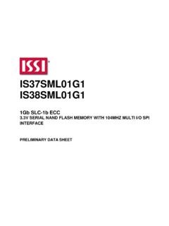
2 FEATURES to supply I2C interface, automatic address increment function Internal reset register Modulate LED brightness with 256 steps PWM Each channel can be controlled independently Each channel can be scaled independently by QFN-44 (5mm 5mm) package QUICK START Figure 1: Photo of IS31FL3236A EVALUATION BOARD RECOMMENDED EQUIPMENT , 2A power supply ABSOLUTE MAXIMUM RATINGS power supply Caution: Do not exceed the conditions listed above, otherwise the BOARD will be damaged. PROCEDURE The IS31FL3236A EVALUATION BOARD is fully assembled and tested. Follow the steps listed below to verify BOARD operation. Caution: Do not turn on the power supply until all connections are completed. 1) Connect the ground terminal of the power supply to the GND and the positive terminal to the VCC.
3 Or connect the DC power to the connector (DC IN) (from version V01C the DC in is replaced by a Micro-USB power in.). 2) Turn on the power supply and pay attention to the supply current. If the current exceeds , please check for circuit fault. 3) Enter the desired mode of display by toggling the MODE button. ORDERING INFORMATION Part No. Temperature Range Package IS31FL3236A-QFLS2-EB -40 C to +85 C (Industrial) QFN-44, Lead-free Table 1: Ordering Information For pricing, delivery, and ordering information, please contacts ISSI s analog marketing team at or (408) 969-6600. 36 channels led driver evaluation board GUIDE Integrated Silicon Solution, Inc. 2 Rev.
4 B, 08/22/2017 EVALUATION BOARD OPERATION The IS31FL3236A EVALUATION BOARD has six display modes. Press MODE button to switch configurations. 1) (Default mode) The 12 RGB LEDs in the middle of the bard show a color changing light bar moving pattern. 2) Two groups of blue LED on above display a tailing effect move from right to left. 3) Two groups of blue LED on above display a tailing effect move in opposite directions. 4) Blue LED on above perform timer display. 5) Two groups of blue LED on above flash together from two sides to middle and then turn off slowly from both sides to middle. 6) The blue LEDs on above are put into four 8 digits and to show a twist effect. Note: IS31FL3236A solely controls the FxLED function on the EVALUATION BOARD . SOFTWARE SUPPORT JP1 default setting is close circuit.
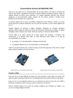
5 If it is set to open, the on- BOARD MCU will stop working. The I2C pins and SDB pin are set to High Impedance. External I2C and SDB signals can be connected to TP3 to control the IS31FL3236A LED DRIVER . GNDSDASCLSDBVCC Figure 2: Photo of Arduino UNO connected to EVALUATION BOARD The steps listed below are an example using the Arduino for external control. The Arduino hardware consists of an Atmel microcontroller with a bootloader allowing quick firmware updates. First download the latest Arduino Integrated Development Environment IDE ( or greater) from Also download the library from and verify that is in the directory ..program Files(x86)/Arduino/hardware/tools/avr/av r/include/avr/. Then download the latest IS31FL3236A test firmware (sketch) from the ISSI website 1) Open JP1. 2) Connect the 5 pins from Arduino BOARD to IS31FL3236A EVB: a) Arduino 5V pin to IS31FL3236A EVB VCC (TP1).
6 B) Arduino GND to IS31FL3236A EVB GND (TP2). c) Arduino SDA (A4) to IS31FL3236A EVB SDA. d) Arduino SCL (A5) to IS31FL3236A EVB SCL. e) If Arduino use MCU VCC, connect to IS31FL3236A EVB SDB, if Arduino use MCU VCC, connect to EVB SDB. (Arduino UNO is , so SDB= ) 3) Use the test code in appendix I or download the test firmware (sketch) from the ISSI website, a .txt file and copy the code to Arduino IDE, compile and upload to Arduino. 4) Run the Arduino code and the initial mode will change the RGB LED brightness every second. Note: the white color LEDs cannot be controlled when the onboard LPC922 is disabled. (Some early BOARD we provided is still controlling the single color LED, if want to switch between single color LED and RGB, remove the U4 and connect the VCC to the LED+) Please refer to the datasheet to get more information about IS31FL3236A.
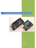
7 36 channels led driver evaluation board GUIDE Integrated Silicon Solution, Inc. 3 Rev. B, 08/22/2017 0 XTAL2 I N10uFC11uFC3TP1TP2JP1 OPEN=EXT EXT40 VCC38 GND17,39 SDA41 SCL42 OUT143 OUT244 OUT31 OUT42 OUT53 OUT64 OUT75 OUT86 OUT97 OUT108 OUT119 OUT1210 OUT1311 OUT1412 OUT1513 OUT1614 OUT1715 SDB36 OUT3635 OUT1918 OUT2019 OUT2120 OUT2221 OUT2322 OUT2423 OUT2524 OUT2625 OUT2726 OUT2827 OUT2928 OUT3029 OUT3130 OUT3231 OUT3332 OUT3433 OUT3534AD37U1IS31FL3236AD1D2D3D8D10D9D4D 5D6D7D18D20D21D19D22D24D25D30D31D32D38D3 9D33D34D35D36D37 OUT1 OUT2 OUT3 OUT4 OUT5 OUT6 OUT7 OUT8 OUT9 OUT1 0 OUT1 8 OUT21 OUT22 OUT25 OUT26 OUT2 7 OUT2 8 OUT2 9 VLEDVLEDD11D12D13D14D15D16D17 OUT1 1 OUT12 OUT13 OUT1 4 OUT1 5 OUT16 OUT17 VLEDOUT1 9 OUT1 9 OUT1 9 OUT1 8 VLEDD23D26D27D28D29 OUT2 3 OUT2 4 VLEDOUT2 0 VLEDVLEDOUT31 OUT32 OUT3 0 OUT3 4 OUT3 3 OUT35 OUT36 GGGGGGGGGGGGRRRRRRRRRRRRBBBBBBBBBBBB Figure 3.
8 IS31FL3236A Application Schematic 36 channels led driver evaluation board GUIDE Integrated Silicon Solution, Inc. 4 Rev. B, 08/22/2017 BILL OF MATERIALS Name Symbol Description Qty Supplier Part No. LED DRIVER U1 36CH FxLED DRIVER 1 ISSI IS31FL3236A LDO U2 Low-dropout Regulator 1 PAM PAM3101 MCU U3 Microcontroller 1 NXP LPC922 PMOS U4 Dual PMOS 1 ANPEC APM4953 Diode D1~D39 Diode, LED Blue, SMD 39 Everlight 19-217/BHC-ZL1M2RY/3T Diode D40~D51 Diode, LED RGB, SMD 12 Everlight 99-235/RGBC/TR8 Resistor R1 RES, ,1/16W, 5%.
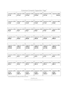
9 SMD 1 Yageo RC0603JR-073K3L Resistor R2~R3 RES, ,1/16W, 5%,SMD 2 Yageo RC0603JR-074K7L Resistor R4~R7 RES,100k,1/16W, 5%,SMD 4 Yageo RC0603JR-07100KL Capacitor C1 CAP,10 F,16V, 20%,SMD 1 Yageo CC0603 KKX7R9BB106 Capacitor C2,C3,C5 CAP, 1 F,16V, 20%,SMD 3 Yageo CC0603 KKX7R9BB105 Capacitor C4 CAP,10nF,16V, 20%,SMD 1 Yageo CC0603 KKX7R9BB103 Button K1 Button SMD 1 Bill of Materials, refer to Figure 3 above. 36 channels led driver evaluation board GUIDE Integrated Silicon Solution, Inc. 5 Rev.
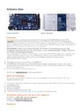
10 B, 08/22/2017 1000001100001234122121 Figure 4: BOARD Component Placement Guide - Top Layer 2100000110000123412212121211212122112121 2121212121212121212121212121212121221212 1212121212121212121121212 Figure 5: BOARD PCB Layout - Top Layer 36 channels led driver evaluation board GUIDE Integrated Silicon Solution, Inc. 6 Rev. B, 08/22/2017 1000001100001234122121 Figure 6: BOARD Component Placement Guide - Bottom Layer 1000001100001212123412212121123456789452 1121221121234521212121987654321987654321 987654321432156781212 Figure 7: BOARD PCB Layout - Bottom Layer Copyright 2017 Integrated Silicon Solution, Inc.