Transcription of 12. Pressure V - Koç Hastanesi
1 1 Pressure VesselsCylindrical or spherical Pressure vessels ( , hydraulic cylinders, gun barrels,pipes, boilers and tanks) are commonly used in industry to carry both liquid s and gasesunder Pressure . When the Pressure vessel is exposed to this Pressure , the materialcomprising the vessel is subjected to Pressure loading, and hence stresses, from alldirections. The normal stresses resulting from this Pressure are functions of the radius ofthe element under consideration, the shape of the Pressure vessel ( , open endedcylinder, closed end cylinder, or sphere) as well as the applied Pressure . Two types of analysis are commonly applied to Pressure vessels.
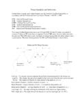
2 The mostcommon method is based on a simple mechanics approach and is applicable to thinwall Pressure vessels which by definition have a ratio of inner radius, r, to wall thickness,t, of r/t 10. The second method is based on elasticity solution and is always applicableregardless of the r/t ratio and can be referred to as the solution for thick wall pressurevessels. Both types of analysis are discussed here, although for most engineeringapplications, the thin wall Pressure vessel can be Pressure VesselsSeveral assumptions are made in this method. 1) Plane sections remain plane2) r/t 10 with t being uniform and constant3) The applied Pressure , p, is the gage Pressure (note that p is thedifference between the absolute Pressure and the atmospheric Pressure )4) Material is linear-elastic, isotropic and ) Stress distributions throughout the wall thickness will not vary6) Element of interest is remote from the end of the cylinder and othergeometric ) Working fluid has negligible weightCylindrical Vessels: A cylindrical Pressure with wall thickness, t, and inner radius,r, is considered, (see Figure 1).
3 A gauge Pressure , p, exists within the vessel by theworking fluid (gas or liquid). For an element sufficiently removed from the ends of thecylinder and oriented as shown in Figure 1, two types of normal stresses aregenerated: hoop, h, and axial, a, that both exhibit tension of the 1 Cylindrical thin - walled Pressure VesselFor the hoop stress, consider the Pressure vessel section by planes sectioned by planesa, b, and c for Figure 2. A free body diagram of a half segment along with thepressurized working fluid is shown in Fig. 3 Note that only the loading in the x-direction is shown and that the internal reactions in the material are due to hoop stressacting on incremental areas, A, produced by the Pressure acting on projected area, equilibrium in the x-direction we sum forces on the incremental segment of width dy tobe equal to zero such that.
4 FApAprtxhphhh =[] ==[] =0202 t dy p 2r dyor solving for (1)where dy = incremental length, t = wall thickness, r = inner radius, p = gauge Pressure ,and h is the hoop 2 Cylindrical thin - walled Pressure vessel Showing Coordinate Axes andCutting Planes (a, b, and c)3 Figure 3 Free-Body Diagram of Segment of Cylindrical thin - walled Pressure VesselShowing Pressure and Internal Hoop StressesFor the axial stress, consider the left portion of section b of the cylindrical pressurevessel shown in Figure 2. A free body diagram of a half segment along with thepressurized working fluid is shown in Fig. 4 Note that the axial stress acts uniformlythroughout the wall and the Pressure acts on the endcap of the cylinder.
5 For equilibriumin the y-direction we sum forces such that:FApAr rrrrrrrrrrttrrrt tyae aoaaoa = == () = ()=[] ()=++ ()=+()0022222222222222222 p or solving for p substituting r = r + t gives p r+tp p since this is a thin wall with a small t,t is smaller and cano2be neglected such that after simplificationbe neglected such that after simplificationp art=2(2)where ro = inner radius and a is the axial 4 Free-Body Diagram of End Section of Cylindrical thin - walled PressureVessel Showing Pressure and Internal Axial StressesNote that in Equations 1 and 2, the hoop stress is twice as large as the axialstress. Consequently, when fabricating cylindrical Pressure vessels from rolled-formedplates, the longitudinal joints must be designed to carry twice as much stress as thecircumferential Vessels: A spherical Pressure vessel can be analyzed in a similarmanner as for the cylindrical Pressure vessel .
6 As shown in Figure 5, the axial stressresults from the action of the Pressure acting on the projected area of the sphere such thatFApAr rrrrrrrrrrttrrrt tyae aoaaoa = == () = ()=[] ()=++ ()=+()0022222222222222222 p or solving for p substituting r = r + t gives p r+tp p since this is a thin wall with a small t,t is smaller and can o2be neglected such that after simplificationbe neglected such that after simplificationp ahrt==2(3)Note that for the spherical Pressure vessel , the hoop and axial stresses are equaland are one half of the hoop stress in the cylindrical Pressure vessel . This makes thespherical Pressure vessel a more efficient Pressure vessel 5 Free-Body Diagram of End Section of Spherical thin - walled Pressure VesselShowing Pressure and Internal Hoop and Axial StressesThe analyses of Equations 1 to 3 indicate that an element in either acylindrical or a spherical Pressure vessel is subjected to biaxial stress ( , a normalstress existing in only two directions).
7 In reality, the element is subjected to a radial stress, rwhich acts along a radial line. The stress has a compressive value equal to thepressure, p, at the inner wall, and decreases through the wall to zero at the outer wall(plane stress condition) since the gage Pressure there is zero. For thin walled pressurevessels, the radial component is assumed to equal zero throughout the wall since thelimiting assumption of r/t=10 results in h being 10 times greater than r=p and a being5 time greater than r=p. Note also that the three normal stresses are principal stressesand can be used directly to determine failure that the relations of Equation 1 to 3 are for internal gauge pressuresonly.
8 If the Pressure vessel is subjected to an external Pressure , it may cause thepressure vessel to become unstable and collapse may occur by buckling of the Pressure VesselsClosed-form, analytical solutions of stress states can be derived using methodsdeveloped in a special branch of engineering mechanics called elasticity. Elasticitymethods are beyond the scope of the course although elasticity solutions aremathematically exact for the specified boundary conditions are particular problems. Forcylindrical Pressure vessels subjected to an internal gage Pressure only the followingrelations result:6 hoioaoiroiorrrrrrrrrrrrr= ()+ = ()= () iiip p p 222222222222211(4)where ro=outer radius, ri=inner radius, and r is the radial variable.
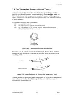
9 Equations 4 applyfor any wall thickness and are not restricted to a particular r/t ratio as are the Equations1 and 2. Note that the hoop and radial stresses( h and r) are functions of r ( through the wall thickness) and that the axial stress, a, is independent of r ( , isconstant through the wall thickness. Figure 6 shows the stress distributions throughthe wall thickness for the hoop and radial stresses. Note that for the radial stressdistributions, the maximum and minimum values occur, respectively, at the outer wall( r=0) and at the ( r=-p) as noted already for the thin walled Pressure 4 can be generalized for the case of internal and external pressuressuch that hoihoihoirr rrrrrrrrrrr rrrrr= () ()= ()=+ () ()ii oo io o iii ooii oo io o ip- pp p /p- pp- pp p /22 22222222222 22222(5)where po=is the outer gauge Pressure and, pi=inner gage ) hoop stressb) radial stressFigure 6 Stress distributions of hoop and radial stresses