Transcription of 15 kV DC Dielectric Test Set Catalog No. 220015 …
1 AVTM22-15Ja Rev A. May 2005. 15 kV DC Dielectric Test Set Catalog No. 220015 Series HIGH-VOLTAGE EQUIPMENT. PLEASE READ CAREFULLY BEFORE OPERATING. Safety is the responsibility of the user APARATO DE VOLTAJE ALTO. SIRVANSE LEER ESTE LIBRO CON CUIDADO. ANTES OE OPERARLO. La seguridad es el cargo del operador M. Copyright 1985-2005 by Megger. All rights reserved. The information presented in this manual is believed to be adequate for the intended use of the product. If the product or its individual instruments are used for purposes other than those specified herein, confirmation of their validity and suitability must be obtained from Megger. Specifications are subject to change without notice. Megger Valley Forge Corporate Center M 2621 Van Buren Avenue Norristown, PA 19403-2329 USA. Tel: 610-676-8500. Fax: 610-676-8610. Table of Contents 1 2 SAFETY 3 RECEIVING 4 5 DESCRIPTION .. 15. Electrical ..15. Power Supply Overcurrent and Overvoltage Trip.
2 18. 6 CONTROL AND CONNECTOR IDENTIFICATION .. 25. 7 SETTING 27. Preparation ..27. Selection of Connections Procedure ..28. Power Supply Option, Catalog No. 8 35. Test Breakdown of Test Item ..36. Normal Shutdown Procedure ..37. Interrupting a Test ..37. 9 OPERATION 39. Line Voltage ..39. Meter Range Settings During Stabilizing Stabilizing Switch (-50 Option)..40. Use of Voltage Control Scale ..41. Use of Regulation Curve (-50 Option) ..42. Step Voltage Fault Locating (Breakdown Testing)..42. External Current i AVTM22-15Ja Rev. A May 2005. M. 10 APPLICATION Theory of Insulation Testing .. 47. Applying the Test Set to Grounded Test 48. Three-Terminal vs. Two-Terminal 49. Measuring an Ungrounded Test 49. Generalized Combined 2 and 3 Terminal 51. 11 ROUTINE MAINTENANCE ..53. 53. Inspection and Maintenance 53. 12 TROUBLESHOOTING AND General .. 57. Case 58. Repairs to Components of Chassis And 58. Changing Line Voltage Tap (-47 Models Only).. 59. Replacement of Output Cable 59.
3 Replacement of Meters or Meter Amplifier Board .. 60. Replacement of Current Meter Range 60. Replacement of Voltmeter Range Circuit .. 60. Replacement of Stabilizing Switch 61. Replacement of Circuit 61. Replacement of Voltage Control Autotransformer 62. Replacement of the K2 Assembly .. 62. Replacement of Chassis-Mounted 62. Replacement of Circuit Card 63. Calibration of 63. Calibration of Current Meter .. 64. Adjustment of R1 in Stabilization Network (-50 Option).. 66. Catalog No. 220015 -50 .. 66. Catalog No. 220015 -47, 67. Trouble Location 68. 13 PERFORMANCE 14 PARTS 15 WARRANTY AND 77. Repairs .. 77. ii AVTM22-15Ja Rev. A May 2005. List of Figures Figure a: The Megger Catalog No. 220015 DC Dielectric Test Figure 1: Schematic Diagram of Catalog No. 19. Figure 2: Schematic Diagram of Catalog No. 20. Figure 3: Schematic Diagram of Catalog No. 21. Figure 4: Schematic Diagram of Catalog No. 22. Figure 5: Schematic Diagram of Catalog No. 23. Figure 6A: Overall View of Catalog No.
4 25. Figure 6B: Panel View of Catalog No. 26. Figure 7: Testing in a 31. Figure 8: Testing Parking Lot Lighting; the Test Set Shown is Operating from an Inverter .. 32. Figure 9: Testing Transformer Terminals.. 33. Figure 10: DC Motor test 34. Figure 11: Generator test 34. Figure 12: Regulation Curves with Stabilizer "out", 120V Supply, -50 44. Figure 13: Typical Guard Connection to Cable 45. Figure 14: Guard Connection for a Typical Cable 45. Figure 15: Typical Guard Connection for an Oil Circuit 46. Figure 16: Typical Guard Connection for Transformer Test .. 46. Figure 17: Two-Winding Transformer in Three-Terminal 50. Figure 18: Interior Views.. 70. Figure 19: Connections for Calibration of 71. Figure 20: Connections for Calibration of the Current 71. iii AVTM22-15Ja Rev. A May 2005. M. List of Tables Table 1: Minimum Air Table 2: Measurements of Table 3: Trouble iv AVTM22-15Ja Rev. A May 2005. 1. INTRODUCTION. This instruction manual is intended as a guide to the operation and maintenance of the portable Dielectric Test Set, Megger Catalog No.
5 220015 series.* References in this manual to optional functions and equipment may be disregarded when such information does not apply to the Test Set in use. The instructions and suggestions provided in this manual anticipate the normal use of the Dielectric Test Set for testing electrical insulation systems on such equipment as motors, generators, bushings and cables. These tests which are based on measurement of the applied dc voltage, the resulting current and the manner in which current varies with time, provide data that indicate the condition of the insulation system of the unit being tested. When these data are recorded on graph paper, such as Megger Kilovolt-Megohm Paper (Part No. 220000), the shape of the curve made by connecting the plotted points will aid in evaluating the conditions of the insulation system. Information on the interpretation of observed data and guides for test voltage and time are given in Section 10 of this manual.
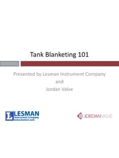
6 The basic available options covered by this manual are: -42 Adjustable overcurrent trip setting on microammeter. -43 Adjustable overvoltage trip setting on kilovoltmeter. -47 Operation from input line voltage other than nominal 115 volts (Specify voltage from 100 to 240 volts). -50 Internal voltage stabilization circuits to suppress input transient voltages. * This manual is intended for use with sets manufactured after January 1985. 1. AVTM22-15Ja Rev. A May 2005. M. Figure a: The Megger Catalog No. 220015 . DC Dielectric Test Set 2. AVTM22-15Ja Rev. A May 2005. 2. SAFETY PRECAUTIONS. SAFETY IS THE RESPONSIBILITY OF THE USER. LA SEGURIDAD ES LA RESPONSABILIDAD DEL OPERADOR. The Test Set and the equipment to which it is connected are a source of high-voltage electrical energy. All persons performing or assisting in the tests must use all practical safety precautions to prevent contact with energized parts of the test equipment and associated circuits.
7 Persons actually engaged in the test must stand clear of all parts of the complete high- voltage circuit unless the Test Set is de-energized and all parts of the test circuit are grounded. Persons not directly associated with the work must be kept away from test activities by suitable barriers, barricades or warnings. The Test Set panel must be connected to a reliable local ground to prevent possible shock danger to the operator. Since the energized test setup may induce a static voltage charge on nearby insulated objects, including people, all insulated objects must be grounded or kept at least two feet (61 cm) from the energized structure. CAUTION! G Never connect the Test Set to energized equipment or use the Test Set in an explosive atmosphere. All apparatus to be tested should be bonded to ground except during the actual test. Note that even isolated conductors may develop static voltage with respect to ground due to nearby electric fields, wind friction or passing electrified clouds.
8 Test connections should be made with the ground bonds in place. 3. AVTM22-15Ja Rev. A May 2005. M. At the completion of a test, after the power source has been shut down and the Test Set kilovoltmeter reads zero, all energized parts of the test setup must be short-circuited by means of a safety grounding stick (hot stick). Ground bonds should then be applied to the equipment that was tested. These bonds should be left in place until access to the equipment is again required. If the Test Set is operated in accordance with the safety precautions noted above and in Sections 7 and 8, and if all grounds are correctly made, rubber gloves are not necessary. As a routine safety procedure however, some users require that rubber gloves be worn not only when making connections to the high-voltage terminals, but also when manipulating controls. Megger considers this an excellent safety practice. Megger strongly recommends the general safety practices contained in IEEE Std.
9 510 "IEEE Recommended Practices for Safety in High-Voltage and High-Power Testing" as a guide for all high-voltage testing. Do not, however, use this standard to reduce any of the precautions given in this manual. HEART PACEMAKERS. High-voltage discharges and other sources of strong electric or magnetic fields may interfere with the proper functioning of heart pacemakers. Personnel using heart pacemakers should obtain expert advice on the possible risks before operating this equipment or being close to the equipment during operation. OTHER PRECAUTIONS. Be especially careful when testing apparatus having high capacitance such as cables. These items store a dangerous charge, even at low voltage. Identify apparatus terminals and verify apparatus ground prior to making connections. 4. AVTM22-15Ja Rev. A May 2005. SAFETY PRECAUTIONS. WARNING! F Do not use the Cat. No. 220015 Series Test Set for any purpose not described in this Instruction Manual, and do not use accessory items (cables, grounding sticks, etc.)
10 For any purpose except with the specified equipment. Read and follow the instruction manual. 5. AVTM21-415Ja Rev. A May 2005. M. M. 6. AVTM22-15Ja Rev. A May 2005. 3. RECEIVING INSTRUCTIONS. When your instrument arrives, check the equipment received against the packing list to ensure that all materials are present. Notify: Megger Valley Forge Corporate Center 2621 Van Buren Avenue Norristown, PA 19403 of any shortage of materials. Examine the instrument for damage received in transit. If any damage is discovered, file a claim with the carrier at once and notify Megger or its nearest authorized sales representative, giving a detailed description of the damage observed. This instrument has been thoroughly tested and inspected to meet rigid inspection specifications before being shipped. It is ready for use when set up as indicated in Section 7. A qualified person should become familiar with this entire Manual and make a test run. This pre-test serves both to familiarize the user with the Test Set and to check that the set is operating properly.