Transcription of 18/30 (36) KV - SINGLE CORE, XLPE INSULATED, …
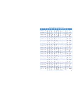
1 DIMENSIONAL CHARACTERISTICS18/30 (36) KV - SINGLE CORE, xlpe insulated , pvc sheathed , screened , unarmoured M6N, M6 AConforming to IEC 60502-2 Radial Thickness ofLengthondrumCableNominal DiametersApproximative net weightInnerSheathConductorInsulationOver allConductorCableConductormm2mmmmmmmmmmm mKg/Km Kg/Km Kg/Km Kg/KmmCurrent carrying capacity **mm2 Copper cableAluminium cableOuterSheathNominalcrosssection DC Resistance at20 C*UndergroundCableCables in ductTrefoilformationAluCables in airNominalcrosssectionInsulationNominali nductance /Km /KmmH/KmmH/Km F/KmAmpAmpAmpAmpAmpAmpCopperAluFlatforma tionNominalcapacityCopperAluCopperAluCop perELECTRICAL * At different operating T( C) : R = R20 C {1+ (T C - 20)} : Temperature coefficient at 20 C = for copper & for aluminium** Laying conditions : - Underground : Temperature of the soil 20 C - Thermal resistivity 100 C cm/w- In air.
2 Ambient temperature 30 C** Greater sizes are also available 37 DIMENSIONAL CHARACTERISTICS18/30 (36) KV - THREE CORE, xlpe insulated , pvc sheathed , screened , unarmoured M6N, M6 AConforming to IEC 60502-2507095120150185240300 Radial Thickness DiametersApproximative net weightInnerSheathConductorInsulationOver allConductorCableConductormm2mmmmmmmmmmm mKg/Km Kg/Km Kg/Km Kg/KmmCopper cableAluminium cableOuterSheathNominalcrosssection carrying capacity **mm2 ELECTRICAL CHARACTERISTICSDC Resistance at20 C*UndergroundCableCables in ductAluCables in airNominalcrosssectionNominalinductance F/KmAmpAmpAmp175220265305345395470535 Amp195235285330375430510585 Amp150185225260295335400455 AmpCopperAluNominalcapacityCopperAluCopp erAluCopper* At different operating T( C) : R = R20 C {1+ (T C - 20)}.
3 Temperature coefficient at 20 C = for copper & for aluminium** Laying conditions : - Underground : Temperature of the soil 20 C - Thermal resistivity 100 C cm/w- In air : Ambient temperature 30 C 38 DIMENSIONAL CHARACTERISTICS18/30 (36) KV - THREE CORE, xlpe insulated , pvc sheathed , screened , DOUBLE STEEL TAPE ARMOURED M6NB, M6 ABConforming to IEC 60502-2507095120150185240300 Radial Thickness DiametersApproximative net weightInnerSheathConductorInsulationOver allConductorCableConductormm2mmmmmmmmmmm mKg/Km Kg/Km Kg/Km Kg/KmmCopper cableAluminium cableOuterSheathNominalcrosssection carrying capacity **mm2 ELECTRICAL CHARACTERISTICSDC Resistance at20 C*UndergroundCableCables in ductAluCables in airNominalcrosssectionNominalinductance F/KmAmpAmpAmp175220265305345395470535 Amp195235285330375430510585 Amp150185225260295335400455 AmpCopperAluNominalcapacityCopperAluCopp erAluCopper* At different operating T( C) : R = R20 C {1+ (T C - 20)}.
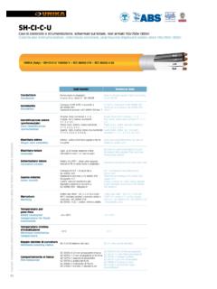
4 Temperature coefficient at 20 C = for copper & for aluminium** Laying conditions : - Underground : Temperature of the soil 20 C - Thermal resistivity 100 C cm/w- In air : Ambient temperature 30 C 391. SCOPEThis specification covers three core overheadinsulated cables, rated 12/20 (24) KVgenerally conforming to IEC ConductorAluminium, circular stranded and compactedconforming to IEC 60228 - Class Conductor ScreeningExtruded thermosetting semi-conductor layer,conforming to IEC InsulationXLPE thermosetting material conforming toIEC 12/20 (24) KV THREE CORE xlpe INSULATEDBUNDLED OVERHEAD CONDUCTORS (TORSADE)OUR types : M5A2T - M5A3T - Insulation Semi conducting screen:Extruded thermosetting semi-conducting layer, applied under a swellablesemi-conducting tape for Metal screen.
5 Plain soft copper wire and / or copper tape applied helically, or aluminiumtape applied longitudinally bonded to the outer PE Outer sheathExtruded black PE sheath, or PVC upon specific customer requirements,conforming to IEC Steel Messenger50 or 70 mm2 steel stranded wires, covered with black PE, or PVC upon specificcustomer TESTSAll tests required by the IEC 60502-2, either on raw materials or on finished products. 4012/20 (24) KV - THREE CORE, xlpe INSULATED, BUNDLED OVERHEAD CONDUCTORS (TORSADE)Type M5A4 TConforming to IEC 60502-2507095120150185240 Current carrying capacity **mm2DC Resistance at20 C*Cables in F/KmAmpAluNominalcapacityDIMENSIONAL CHARACTERISTICSL engthondrum DiametersConductorConductorCablemm2mmmmm mKg/Km Kg/KmmOuterSheathNominalcrosssection * At different operating T( C) : R = R20 C {1+ (T C - 20)} : Temperature coefficient at 20 C = for copper & for aluminium** Laying conditions : - Underground : Temperature of the soil 20 C - Thermal resistivity 100 C cm/w- In air.
6 Ambient temperature 30 C** Greater sizes are also availableSuspensionStrandOverJacketOverb unchedConductorsmm67727578818590 Approximativenet CHARACTERISTICSN ominalcrosssectionRadial Thickness of3x50 / 163x70 / 163x95 / 163x120 / 163x150 / 253x185 / 253x240 / 25 41 x S Ux u U2 L Ix FormulaeU = RI2Lx SP(w) = U IP(w) = U I cos P (w)UP(VA) P (W)U cos U P(VA) P (W)U 3 cos U 3W = RI2 tP(w) = 3 U I cos Ohms lawJoules lawResistance of a line(feed and return)DC PowerSingle phase PowerThree phase PowerAC SINGLE core currentDC CurrentAC Three phase currentEfficiencyP outputP input Voltage dropThree phasesystemVoltage dropSize u (v)mm2If current known2 L Ix uIf power known2 L P(w)2L P(w)x S Ux u UIf current L I cos L I cos x Sx uIf power knownL P(w)L P(w)Nature of the currentSingle phaseAC/DC systemsUIRWtL1x11S1P1 Cos e u=11===1==1=11=1=1===Rated Voltage in V(volts)(between phase in threephase system).
7 Current in A (Amperes).Resistance in (ohms).Energy in Ws (Wattsecond).Time in s (second)Length of cable in m(meter).Conductivity (56 forcopper and 34 forAluminium).Cross sectional area in W (Watt) orVA (Volt Ampere).Power drop sending toreceiving end of line inV(Volts).R=I=I==I==e= u = u = u = u =S =S =S =S =7 TECHNICAL INFORMATION Conversion factors and unitsThe SI unit for power is the W1W = Kgm / s = x 10-3 HP = BTU / h1 Kgm / s = W = HP = BTU / h1HP = W = 75 Kgm / s = 2510 Btu /h1 BTu /h = W = Kgm / s = x 10-3 HPw = watt, Kgm / s = Kilogramme meter per second,HP = metric Horse power, BTU /h = British thermal unit per hourThe SI unit for force is the N1N = Kgf = Lbf1 Kgf = N = Lbf1 Lbf = N = KgfN = Newton, Kgf = Kilogram force.
8 Lbf = pound forceThe SI unit for length is the m1m = 102 cm = 103 mm = 10-3 Km1m = in = ft = Yd = x 10-3 miles1 in = m = ft = Yd = x 10-3 miles1 ft = m = 12 in = Yd = x 10-3 miles1 Yd = m = 36 in = 3 ft = x 10-3 miles1 mile = 1609 m = 63360 in = 5280 ft = 1760 Ydm = meters, in = inches, ft = feet, Yd = YardsThe SI unit for volume is the m31m3 = 10 dm3 = 106 cm3 = 109 mm31m3 = 1000 L = ft3 = = gal1L = m3 = ft3 = = gal1 ft3 = m3 = L = = gal1 = x 10-3 m3 = L = ft3 = gal1 gal = x 10-3 m3 = L = ft3 = I. gall = liters, ft = feet, = Imperial gallon, = United States gallonLength :Weight :Volume :Force :Power : The SI unit for weight is the Kg1 Kg = 103 g = 10-3 T (metric ton)1 Kg = lb = oz1 oz = x 10-3 Kg = lbKg = Kilogrammes, lb = pounds, oz = ounces 43 The SI unit for pressure is the Pa = 1 N/m21 N /m2 = 10-5 Kgf / cm2 = 10-5 bar1 Kgf / cm2 = 105 N / m2 = 1 barPa = Pascal, N/m2 = Newton per square meterKgf / cm2 = Kilogramme force per square centimeterPressure :Work : The SI unit for work is the J1J = 1Ws (Wattsecond) = 1Nm (Newton meter)1J = x 10-6 Kwh = x 10-3 Kcal1 Kwh = x 106 J = Kcal1 Kcal = J = x 10-3 KwhJ = Joules, Kwh = Kilowatt hour, Kcal = KilocaloriesTemperature.
9 The SI unit for Temperature is the Kelvin (K)Temperature in o C = Temperature in o K - 273 = 5/9 (Temperature in o F - 32)Temperature in o K = Temperature in o C + 273o C = degree celcius, o K = degree Kelvin, o F = degree Fahrenheit 44 When several cables or ducts are laid underground with less than one meter spacing thecurrent rating values should be multiplied by the following correction factors :Number ofcircuitsTouchingcablesOne diameterspaced cablesa = = = = 2. CABLES LAID IN AIR :The stated values are for cables or ducts laid in air with an ambient temperature of30 C and out of direct sunlight, spaced so that the temperature rise of individual cableshas no influence on others. The spacing between adjacent cables is at least twice thecable or duct the ambient temperature is different ( not 30 C ) the current rating values shouldbe multiplied by the following correction factors :Ambienttemperature ( C)05101520253035404550556065707580859095 100 Carrying core temperature ( C) factor of proximity effect for underground cablesD = overall outer sheath diameter a = Space between cablesCorrection factor for different ambient temperatureSingle or multicore cables 11 When several cables or ducts are grouped, the current ratings values should be correctedas follows.
10 ADHSINGLE CORE CABLESM ethodof layingTouchingOne diameterspaced cablesa = DNumber of layers123123 Number of cables inhorizontal layer3 cables intriangular formationMULTICORE CABLESM ethodof layingTouchingOne diameterspaced cablesa = DNumber of layers123123 Number of : the space H between layers must not be less than InductanceThe Inductance L depends on the geometrical characteristics of the cable as well as thedisposition of conductorsfor unarmoured cables Conductors short - circuit current :Current densities given in the table below are in (A / mm2 ), for a maximum condutortemperature of 250 C at the end of the short - of conductorbefore overloadT ( C )20307090overload time in metalCurrent density ( A / mm2 )For an overload duration (t) different than those figured in the above table, thecorrespondant current density is given by the following formula.