Transcription of 19 - Talking Electronics
1 506 Principles of ElectronicsIn the previous chapters, we have discussed the cir-cuit applications of an ordinary transistor . In thistype of transistor , both holes and electrons play partin the conduction process. For this reason, it is some-times called a bipolar transistor . The ordinary or bipo-lar transistor has two principal disadvantages. First, ithas a low input impedance because of forward biasedemitter junction. Secondly, it has considerable noiselevel. Although low input impedance problem may beimproved by careful design and use of more than onetransistor, yet it is difficult to achieve input impedancemore than a few megaohms.
2 The field effect transistor (FET) has, by virtue of its construction and biasing, largeinput impedance which may be more than 100megaohms. The FET is generally much less noisy thanthe ordinary or bipolar transistor . The rapidly expand-ing FET market has led many semiconductor market- of field effect Transis-tors and Working of JFET of JFET as an Amplifier Features of for Drain Current(ID) of ofTransconductance (gm or gfs)of Biasing by Bias with Voltage-Divider JFET Load Line Gain of JFET Amplifier(With Source Resistance Rs) Oxide SemiconductorFET (MOSFET)
3 For Transfer Versus Biasing CircuitsINTRODUCTIONF ield EffectTransistors19 field effect Transistors 507ing managers to believe that this device will soon become the most important electronic device,primarily because of its integrated-circuit applications. In this chapter, we shall focus our attentionon the construction, working and circuit applications of field effect Types of field effect TransistorsA bipolar junction transistor (BJT) is a current controlled device , output characteristics of thedevice are controlled by base current and not by base voltage. However, in a field effect transistor (FET), the output characteristics are controlled by input voltage ( , electric field ) and not by inputcurrent.
4 This is probably the biggest difference between BJT and FET. There are two basic types offield effect transistors:(i)Junction field effect transistor (JFET)(ii)Metal oxide semiconductor field effect transistor (MOSFET)To begin with, we shall study about JFET and then improved form of JFET, namely; Junction field effect transistor (JFET)A junction field effect transistor is a three terminal semiconductor device in which current conduc-tion is by one type of carrier , electrons or JFET was developed about the same time as the transistor but it came into general use onlyin the late 1960s. In a JFET, the current conduction is either by electrons or holes and is controlled bymeans of an electric field between the gate electrode and the conducting channel of the device.
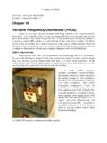
5 TheJFET has high input impedance and low noise details. A JFET consists of a p-type or n-type silicon bar containing two pnjunctions at the sides as shown in The bar forms the conducting channel for the chargecarriers. If the bar is of n-type, it is called n-channel JFET as shown in Fig. (i) and if the bar isof p-type, it is called a p-channel JFET as shown in Fig. (ii). The two pn junctions formingdiodes are connected *internally and a common terminal called gate is taken out. Other terminals aresource and drain taken out from the bar as shown. Thus a JFET has essentially three terminals viz.
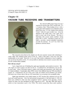
6 ,gate (G), source (S) and drain (D).Fig. *It would seem from Fig. that there are three doped material regions. However, this is not the case. Thegate material surrounds the channel in the same manner as a belt surrounding your waist. 508 Principles of ElectronicsJFET polarities. Fig. (i) shows n-channel JFET polarities whereas Fig. (ii) shows thep-channel JFET polarities. Note that in each case, the voltage between the gate and source is suchthat the gate is reverse biased. This is the normal way of JFET connection. The drain and sourceterminals are interchangeable , either end can be used as source and the other end as following points may be noted :(i)The input circuit ( gate to source) of a JFET is reverse biased.
7 This means that the devicehas high input impedance.(ii)The drain is so biased source that drain current ID flows from the source to drain.(iii)In all JFETs, source current IS is equal to the drain current IS = Principle and Working of JFETFig. shows the circuit of n-channel JFET with normal polarities. Note that the gate is The two pn junctions at the sides form two depletion layers. The current conduction bycharge carriers ( free electrons in this case) is through the channel between the two depletion layersand out of the drain. The width and hence *resistance of this channel can be controlled by changing theinput voltage VGS.
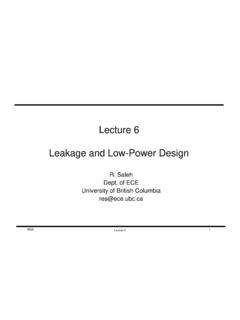
8 The greater the reverse voltage VGS, the wider will be the depletion layers and nar-rower will be the conducting channel. The narrower channel means greater resistance and hence sourceto drain current decreases. Reverse will happen should VGS decrease. Thus JFET operates on the prin-ciple that width and hence resistance of the conducting channel can be varied by changing the reversevoltage VGS. In other words, the magnitude of drain current (ID) can be changed by altering The working of JFET is as under :(i)When a voltage VDS is applied between drain and source terminals and voltage on the gate iszero [ See Fig.]
9 (i) ], the two pn junctions at the sides of the bar establish depletion layers. Theelectrons will flow from source to drain through a channel between the depletion layers. The size ofthese layers determines the width of the channel and hence the current conduction through the bar.(ii)When a reverse voltage VGS is applied between the gate and source [See Fig. (ii)], thewidth of the depletion layers is increased. This reduces the width of conducting channel, therebyincreasing the resistance of n-type bar. Consequently, the current from source to drain is the other hand, if the reverse voltage on the gate is decreased, the width of the depletion layersalso decreases.
10 This increases the width of the conducting channel and hence source to drain current.*The resistance of the channel depends upon its area of X-section. The greater the X-sectional area of thischannel, the lower will be its resistance and the greater will be the current flow through it. field effect Transistors 509 Fig. is clear from the above discussionthat current from source to drain can becontrolled by the application of potential( electric field ) on the gate. For thisreason, the device is called field effecttransistor. It may be noted that a p-chan-nel JFET operates in the same manner asan n -channel JFET except that channelcurrent carriers will be the holes insteadof electrons and the polarities of VGS andVDS are If the reverse voltage VGS on thegate is continuously increased, a state isreached when the two depletion layers toucheach other and the channel is cut off.