Transcription of 1F80-51 (37-5285E) - climate.emerson.com
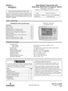
1 To prevent electrical shock and/or equipment damage,disconnect electric power to system at main fuse orcircuit breaker box until installation is not use on circuits exceeding specified voltage will damage control and could causeshock or fire not short out terminals on gas valve or primarycontrol to test. Short or incorrect wiring will damagethermostat and could cause personal injury and/orproperty TO READ AND FOLLOW ALL INSTRUCTIONS CAREFULLYBEFORE INSTALLING OR OPERATING THIS CONTROL COULD CAUSEPERSONAL INJURY AND/OR PROPERTY new White-Rodgers 5-Day/2-Day Digital Thermostat usesthe technology of a solid-state microcomputer to provide pre-cise time/temperature control. This thermostat offers you theflexibility to design heating and cooling programs that fit : Battery powered (3 AA Energizer alkaline batteries in-cluded). Separate 5-day (weekday) and 2-day (weekend) programming Simultaneous heat and cool program storage Preprogrammed temperature control Four separate time/temperature settings per 24-hour period LCD continuously displays set point, and alternately dis-plays time and room temperature Temperature override until next program period Manual program override (HOLD temperature) User may select either 12- or 24-hour clock display F/ C convertibility Temperature range 45 to 90 F Standard five terminals for single or two-transformer sys-tems B and O terminals for single stage heat pumps or damperoperationSPECIFICATIONSELECTRICAL DATAE lectrical Rating:8 to 30 VAC 50/60 Hz.
2 Or to Amps (Load per terminal) Amps Maximum Total Load (All terminals combined)THERMAL DATAS etpoint Temperature Range:45 F to 90 F (7 C to 32 C)Operating Ambient Temperature Range:32 F to 105 FOperating Humidity Range:0 to 90% RH (non-condensing)Shipping Temperature Range:-40 F to 150 FAPPLICATIONSFor use with: Standard heat/cool or heat only systems Electric heat systems Gas or oil fired systems Gas systems with intermittent ignition devices ( )and/or vent dampers Hydronic (hot water or steam) systems Single-stage heat pump systems Millivolt systemsDO NOT USE WITH: Multi-stage systems Systems exceeding 30 VAC and amps 3-wire zoned hydronic heating systems1F80-51 Programmable Electronic Digital ThermostatPrinted in NO. 37-5285 EReplaces 37-5285D0004 WHITE-RODGERS DIVISIONEMERSON ELECTRIC REAVIS ROADST. LOUIS, MISSOURI 63123-5398 WHITE-RODGERSINSTALLATION ANDOPERATION INSTRUCTIONSPRECAUTIONSCAUTION!
3 This thermostat is intended for use with a low voltage system;do not use this thermostat with a line voltage system. If in doubtabout whether your wiring is millivolt, line, or low voltage, haveit inspected by a qualified heating and air conditioning contrac-tor or not exceed the specification wiring must conform to local and national electrical codesand control is a precision instrument, and should be handledcarefully. Rough handling or distorting components could causethe control to !Operator: Save these instructions for future use!2 INSTALLATIONREMOVE OLD THERMOSTAT1. Shut off electricity at the main fuse box until installation iscomplete. Ensure that electrical power is Remove the front cover of the old thermostat. With wiresstill attached, remove wall plate from the wall. If the oldthermostat has a wall mounting plate, remove the thermostatand the wall mounting plate as an each wire attached to the old thermostat using thelabels enclosed with the new Disconnect the wires from old thermostat one at a time.
4 DONOT LET WIRES FALL BACK INTO THE Install new thermostat using the following HEAT OR SINGLE-STAGEHEAT PUMP SYSTEMSRead entire paragraph before setting electric heat switch. If youare unsure of your application, contact a qualified you have a single-stage heat pump system, OR your systemuses central electric heat, where the blower is energized by aseparate circuit through the fan relay (meaning that the fanturns on immediately on call for heat), then the switch on theback of the thermostat base must be moved to the ELECTRIC position (see fig 1). If the thermostat is energizing electric heatsequencers, the switch MUST remain in the GAS you must move the switch to the ELECTRIC position (to theleft), use a small screwdriver or THERMOSTAT BASE TO WALL1. Remove the packing material from the thermostat. Gentlypull the cover straight off the base. Forcing or prying on thethermostat will cause damage to the unit.
5 If necessary, movethe electric heat switch (see ELECTRIC HEAT SYSTEMS,above).2. Connect wires beneath terminal screws on base usingappropriate wiring schematic (see figs. 3 through 10).3. Place base over hole in wall and mark mounting holelocations on wall using base as a Move base out of the way. Drill mounting Fasten base loosely to wall, as shown in fig. 2, using twomounting screws. Place a level against bottom of base,adjust until level, and then tighten screws. (Leveling is forappearance only and will not affect thermostat operation.) Ifyou are using existing mounting holes, or if holes drilled aretoo large and do not allow you to tighten base snugly, useplastic screw anchors to secure Push excess wire into wall and plug hole with a fire-resistantmaterial (such as fiberglass insulation) to prevent drafts fromaffecting thermostat LOCATIONThis thermostat requires 3 AA alkaline batteries to are installed in the thermostat at the factory with abattery tag to prevent power drainage.
6 You must remove thebattery tag to engage the batteries and provide power to the word BATTERY is displayed, the batteries are low andshould be replaced with fresh AA Energizer alkaline replace the batteries, install the batteries along the top of thebase (see fig. 2). The batteries must be installed with thepositive (+) ends to the (HOT WATER OR STEAM)HEATING SYSTEMSThis thermostat is set to operate properly if you have a forced-air heating system. If you have a hydronic heating system (asystem that heats with hot water or steam), you must set thethermostat to operate properly with your system. While in theHEAT mode, change the setting by pressing and holding SETTIME and VIEW PRGM buttons at the same time until the correctsetting is displayed (A for forced air; H for hydronic systems). Ifthere is a loss of battery power, or when you change batteries,you must repeat this operation once battery power is you do not press both buttons at the same time, A or H will notbe displayed.
7 If this happens, press RUN PRGM, then press andhold SET TIME and VIEW PRGM at the same 1. Back of thermostat baseElectric/Gas switchFigure 2. Thermostat baseMountingholesScrew anchorsAlkaline batteries (3 "AA" install "+" ends to the left)WRHBYOGRC3 RHY24 VAC120 VACHotNeutralTHERMOSTATSYSTEMGWF igure 8. Typical wiring diagram forheat/cool, 5-wire, two-transformer systemsHEATING TRANSFORMERH eatingSystemFanRelayCoolingSystemRC24 VAC120 VACHotNeutralCOOLING TRANSFORMEROBRHY24 VAC120 VACHotNeutralTHERMOSTATSYSTEMGWF igure 7. Typical wiring diagram forheat/cool, 4-wire, single transformer systemsTRANSFORMERH eatingSystemFanRelayCoolingSystemRCJUMPE RWIRERED jumper wire (provided with thermostat) must be connected between thermo-stat's RH and RC terminals for proper thermostat oper-ation with this Series 10 Primary Control(located at furnace)Add jumper wire(not provided with thermostat)Figure 4.
8 Typical wiring diagram for3-wire SERIES 10 heating systemsFurnaceJumper wire must be added between R and B terminals on the primary control (jumper wire not provided with thermostat).NOTERHY24 VAC120 VACHotNeutralTHERMOSTATSYSTEMGWF igure 5. Typical wiring diagram forheat only, 3-wire, single transformer systemsTRANSFORMERH eatingSystemFanRelayYRCJUMPERWIRERED jumper wire (provided with thermostat) must be connected between thermo-stat's RH and RC terminals for proper thermostat oper-ation with this VAC120 VACHotNeutralTHERMOSTATSYSTEMGWF igure 10. Typical wiring diagram forheat pump with heat active reversing valveTRANSFORMERR eversingValve*RCOBJUMPERWIREC ompressorContactorJUMPERWIRE* Reversing valve is energized when the system switch is in the HEAT positionFanRelayRHYTHERMOSTATSYSTEMGWF igure 3. Typical wiring diagram for heating only,2-wire, single transformer systems or millivolt systemsHeatingSystemRCOB24 VAC TransformerorThermopileRHY24 VAC120 VACHotNeutralTRANSFORMERTHERMOSTATSYSTEM GWF igure 6.
9 Typical wiring diagram forcool only, 3-wire, single transformer systemsCoolingSystemFanRelayRCOBRHY24 VAC120 VACHotNeutralTHERMOSTATSYSTEMGWF igure 9. Typical wiring diagram forheat pump with cool active reversing valveTRANSFORMERR eversingValve*RCOBJUMPERWIREC ompressorContactorJUMPERWIRE* Reversing valve is energized when the system switch is in the COOL positionFanRelayCHECK THERMOSTAT OPERATIONIf at any time during testing your system does not operateproperly, contact a qualified OperationIf your system does not have a G terminal connection, skip toHeating Turn on power to the Move fan switch to ON position. The blower should begin Move fan switch to AUTO position. The blower should System1. Move SYSTEM switch to HEAT position. If the heatingsystem has a standing pilot, be sure to light Press to adjust thermostat setting above room tempera-ture.
10 The heating system should begin to Press to adjust temperature setting below room tempera-ture. The heating system should stop SystemThis thermostat has a built-in short-term (5-minute) time feature is activated after the compressor shuts down andthe setpoint is changed within the 5-minute period. During this5-minute period, COOL will flash on the display indicating thatthe thermostat has locked out the compressor to allow headpressure to stabilize. This thermostat does not sense AC powerloss and therefore does not activate the short term compressorprotection feature when power is prevent compressor and/or property damage, if theoutdoor temperature is below 50 F, DO NOT operatethe cooling Move SYSTEM switch to COOL Press to adjust thermostat setting below room tempera-ture. The blower should come on immediately on high speed,followed by cold air circulation3.