Transcription of 2.2.2. DEGREE OF COLORATION OF LIQUIDS - …
1 DEGREE of COLORATION of liquidsEUROPEAN PHARMACOPOEIA suspensions containing small particles. Linearity betweenturbidity and concentration must be established by constructinga calibration curve using at least 4 TURBIDIMETRYIn ratio turbidimetry the relationship of the transmissionmeasurement to the 90 scattered light measurement isdetermined. This procedure compensates for the light thatis diminished by the colour of the sample. The influence ofthe colour of the sample may also be eliminated by usingan infrared light-emitting diode (IR LED) at 860 nm as thelight source of the instrument. The instrument s photodiodedetectors receive and measure scattered light at a 90 anglefromthesampleaswellasmeasuringthefo rward scatter (lightreflected) in front of the sample along with the measurement oflight transmitted directly through the sample. The measuringresults are given in NTU(ratio) and are obtained by calculatingthe ratio of the 90 angle scattered light measured to thesum of the components of forward scattered and transmittedlight values.
2 In ratio turbidimetry the influence of stray lightbecomes negligible. Nephelometers are used for measurementsof the DEGREE of opalescence of colourless of reference suspensions I-IV with a ratioturbidimeter show a linear relationship between theconcentrations and measured NTU values (see Table ).Reference suspensions I-IV (Ph. Eur.) may be used as calibratorsfor the suspensionsOpalescent values (NTU)Reference suspension I3 Reference suspension II6 Reference suspension III18 Reference suspension IV30 Standard of opalescence60 Primary opalescent suspension4000 INSTRUMENTAL DETERMINATION OF OPALESCENCER equirements in monographs are expressed in terms ofthe visual examination method with the defined referencesuspensions. Instrumental methods may also be used fordetermining compliance with monograph requirements oncethe suitability of the instrument as described below has beenestablished and calibration with reference suspensions I-IV andwithwater Ror the solvent used has been Ratio turbidimeters or nephelometers withselectable ratio application use as light source a tungsten lampwith spectral sensitivity at about 550 nm operating at a filamentcolourtemperatureof2700K,orIRLED havinganemissionmaximum at 860 nm with a 60 nm spectral bandwidth.
3 Othersuitable light sources may also be used. Silicon photodiodes andphotomultipliers are commonly used as detectors and recordchanges in light scattered or transmitted by the sample. Thelight scattered at 90 is detected by the primary detectors are those to detect back and forward scatter aswell as transmitted light. The instruments used are calibratedagainst standards of known turbidity and are capable ofautomatic determination of turbidity . The test results expressedin NTU units are obtained directly from the instrument andcompared to the specifications in the individual complying with the following specifications aresuitable. Measuring units: NTU. NTU is based on the turbidity ofa primary reference standard of formazin. FTU (FormazinTurbidity Units) or FNU (Formazin Nephelometry Units) arealso used, and are equivalent to NTU in low regions (up to40 NTU). These units are used in all 3 instrumental methods(nephelometry, turbidimetry and ratio turbidimetry). Measuring range: NTU.
4 Resolution: NTU within the range of 0-10 NTU, NTUwithin the range of 10-100 NTU, and 1 NTU for the range >100 NTU. The instrument is calibrated and controlled withreference standards of formazin. Accuracy:0-10 NTU: (2percentofreading+ ) : 5percent. Repeatability: 0-10 NTU: NTU. 10-1000 NTU: 2 percent of the measured value. Calibration: with 4 reference suspensions of formazin in therange of interest. Reference suspensions described in thischapter or suitable reference standards calibrated againstthe primary reference suspensions may be used. Stray light: this is a significant source of error in low levelturbidimetric measurement; stray light reaches the detectorof an optical system, but does not come from the sample;< ,< complying with the above characteristics andverified using the reference suspensions described underVisual method may be used instead of visual examination fordetermination of compliance with monograph with range or resolution, accuracy and repeatabilitycapabilities other than those mentioned above may be usedprovided they are sufficiently validated and are capable forthe intended use.
5 The test methodology for the specificsubstance/product to be analysed must also be validated todemonstrate its analytical capability. The instrument andmethodology should be consistent with the attributes of theproduct to be DEGREE OF COLORATION OFLIQUIDSThe examination of the DEGREE of COLORATION of LIQUIDS in therange brown-yellow-red is carried out by one of the 2 methodsbelow, as prescribed in the it has the appearance ofwater Rorthe solvent or is not more intensely coloured than referencesolution IUsing identical tubes of colourless, transparent, neutral glass of12 mm external diameter, compare mL of the liquid to beexamined with mL ofwater Ror of the solvent or of thereference solution (see Tables of reference solutions) prescribedin the monograph. Compare the colours in diffused daylight,viewing horizontally against a white IIUsing identical tubes of colourless, transparent, neutral glasswith a flat base and an internal diameter of 15 mm to 25 mm,compare the liquid to be examined withwater Ror the solventor the reference solution (see Tables of reference solutions)prescribed in the monograph, the depth of the layer being40 mm.
6 Compare the colours in diffused daylight, viewingvertically against a white solutionsYellow solution. Dissolve 46 g offerric chloride Rin about900 mL of a mixture of 25 mL ofhydrochloric acid Rand975 mL ofwater Rand dilute to mL with the samemixture. Titrate and adjust the solution to contain mg ofFeCl3,6H2O per millilitre by adding the same acidic the solution from the information section on general monographs (cover pages)EUROPEAN PHARMACOPOEIA DEGREE of COLORATION of liquidsTitration. Place in a 250 mL conical flask fitted with aground-glass stopper, mL of the solution, 15 mL ofwater R,5mLofhydrochloric acid Rand 4 g ofpotassium iodide R,close the flask, allow to stand in the dark for 15 min and add100 mL ofwater R. Titrate the liberated iodine Msodium thiosulfate, solution R, addedtowards the end of the titration, as M sodium thiosulfateis equivalent to mg ofFeCl3, chloride Rin about900mLofamixtureof25mLofhydrochloric acid Rand975 mL ofwater Rand dilute to mL with the samemixture.
7 Titrate and adjust the solution to contain mg ofCoCl2, Place in a 250 mL conical flask fitted with aground-glass stopper, mL of the solution, 5 mL ofdilutehydrogen peroxide solution Rand 10 mL of a 300 g/L solutionofsodium hydroxide R. Boil gently for 10 min, allow to cooland add 60 mL ofdilute sulfuric acid Rand 2 g ofpotassiumiodide R. Close the flask and dissolve the precipitate byshaking gently. Titrate the liberated iodine M sodiumthiosulfate, solution R,addedtowardsthe end of the titration, as indicator. The end-point is reachedwhen the solution turns M sodium thiosulfateis equivalent to mgof CoCl2, primary sulfate Rinabout 900 mL of a mixture of 25 mL ofhydrochloric acid Rand 975 mL ofwater Rand dilute to mL with the samemixture. Titrate and adjust the solution to contain mg ofCuSO4,5H2O per millilitre by adding the same acidic Place in a 250 mL conical flask fitted with aground-glass stopper, mL of the solution, 50 mL ofwater R,12 mL ofdilute acetic acid Rand 3 g ofpotassium iodide the liberated iodine M sodium thiosulfate,using mL ofstarch solution R, added towards the end ofthe titration, as indicator.
8 The end-point is reached when thesolution shows a slight pale brown M sodium thiosulfateis equivalent to mg ofCuSO4, solutionsUsing the 3 primary solutions, prepare the 5 standard solutionsas follows:Table in millilitresStandard solutionYellowsolutionRedsolutionBluesol utionHydrochloric acid(10 g/L HCl)B(brown) (brownish-yellow) (yellow) (greenish-yellow) (red) solutions for Methods I and IIUsing the 5 standard solutions, prepare the following -Reference solutions BVolumes in millilitresReferencesolutionStandard solution BHydrochloric acid(10 g/L HCl) -Reference solutions BYVolumes in millilitresReferencesolutionStandard solution BYHydrochloric acid(10 g/L HCl) -Reference solutions YVolumes in millilitresReferencesolutionStandard solution YHydrochloric acid(10 g/L HCl) -Reference solutions GYVolumes in millilitresReferencesolutionStandard solution GYHydrochloric acid(10 g/L HCl) Notices (1) apply to all monographs and other Potentiometric determination of pHEUROPEAN PHARMACOPOEIA -Reference solutions RVolumes in millilitresReferencesolutionStandard solution RHydrochloric acid(10 g/L HCl)
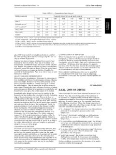
9 Method I, the reference solutions may be stored in sealedtubes of colourless, transparent, neutral glass of 12 mm externaldiameter, protected from Method II, prepare the reference solutions immediatelybefore use from the standard POTENTIOMETRICDETERMINATION OF pHThe pH is a number which represents conventionally thehydrogen ion concentration of an aqueous solution. Forpractical purposes, its definition is an experimental one. ThepH of a solution to be examined is related to that of a referencesolution (pHs) by the following equation:in whichEis the potential, expressed in volts, of the cellcontaining the solution to be examined andEsis the potential,expressed in volts, of the cell containing the solution of knownpH (pHs),kis the change in potential per unit change in pHexpressed in volts, and calculated from the Nernst Values of k at different temperaturesTemperature ( C)k(V) potentiometric determination of pH is made by measuringthe potential difference between 2 appropriate electrodesimmersed in the solution to be examined: 1 of these electrodesis sensitive to hydrogen ions (usually a glass electrode) andthe other is the reference electrode (for example, a saturatedcalomel electrode).
10 Apparatus. The measuring apparatus is a voltmeter with aninput resistance at least 100 times that of the electrodes is normally graduated in pH units and has a sensitivity suchthat discrimination of at least pH unit or at least Vmay be Unless otherwise prescribed in the monograph, allmeasurements are made at the same temperature (20-25 C).Table shows the variation of pH with respect totemperature of a number of reference buffer solutions used forcalibration. For the temperature correction, when necessary,follow the manufacturer s instructions. The apparatus iscalibrated with the buffer solution of potassium hydrogenphthalate (primary standard) and 1 other buffer solution ofdifferent pH (preferably one shown in Table ). The pHof a third buffer solution of intermediate pH read off on thescale must not differ by more than pH unit from the valuecorresponding to this solution. Immerse the electrodes in thesolution to be examined and take the reading in the sameconditions as for the buffer the apparatus is in frequent use, checks must be carriedout regularly.