Transcription of 2. Operational Amplifiers
1 2. Operational AmplifiersTLT-8016 Basic Analog Circuits2005/200612. Operational Amplifiers2. Operational AmplifiersTLT-8016 Basic Analog Circuits2005/20062 Figure Circuit symbol for the op amplifier : A differential amplifier with very high voltage gain. Usually realized as integrated Operational AmplifiersTLT-8016 Basic Analog Circuits2005 The Ideal Operational AmplifierIdeal Operational amplifier : Infinite input impedance. Infinite open loop gain AOLfor differential signal. Zero gain for the common -mode signal. Zero output impedance. Infinite Equivalent circuit for the ideal op amp. AOLis very large (approaching infinity).Common-mode input signal)(2121vvvicm+=Differential input signal21vvvid =Figure Op-amp symbol showing power Operational AmplifiersTLT-8016 Basic Analog Circuits2005 The Summing-Point Constraint Operational Amplifiers are almost always used with negative feedback, in which part of the op-amp output signal is returned to the input in opposition to the source op-amp circuits are analyzed by the following steps:1.
2 Verify that the negative feedback is present. Usually this takes the form of a resistor network connected to the output terminal and to the inverting input Assume that the differential input voltage and the input current of the op amp are forced to zero. (This is summing -point constraint.)3. Apply standard circuit analysis principles, such as Kirchhoff s laws and Ohm s law, to solve for the quantities of Operational AmplifiersTLT-8016 Basic Analog Circuits2005 The Inverting Amplifier11 Rviin=12ii=( )( )12 Rviin=( )Figure Inverting amplifier .( )022=+iRvo12 RRvvAinov ==11 RivZinin==iovRRv12 =vois independent of the load resistance RL. Thus the output acts as ideal voltage source and output impedance is 0.
3 ( )( )( )Figure We make use of the summing-point constraint in the analysis of the inverting Operational AmplifiersTLT-8016 Basic Analog Circuits2005/20066 The Virtual-Short-Circuit ConceptFigure We make use of the summing-point constraint in the analysis of the inverting amplifier . The voltage between both inputs of the Op Amps is forced to be 0. There is no short circuit between both inputs because the current is also 0. The circuit between both inputs is called virtual-short-circuit: v= 0; i= Operational AmplifiersTLT-8016 Basic Analog Circuits2005/20067 Exercise Summing AmplifierA circuit known as a summing amplifieris illustrated in Figure (a) Use the ideal-op-amp assumption to solve for the output voltage in terms of the input voltages and resistor values.
4 (b) What is the input resistance seen by vA? (c) By vB? (d) What is the output resistance seen by RL?Solution: + = =+=+===BfBAfAffoBBAABAfBBBAAARRvRRvRivRv RviiiRviRviFigure Summing amplifier . +-+-+-RARBRfRLvo+-vBvAiAiBifv=0 Input impedance seen by vA: RAInput impedance seen by vB: RBvodoesn t depend on RL, thus the output impedance is Operational AmplifiersTLT-8016 Basic Analog Circuits2005/20068 Exercise Find an expression for the output voltage of the circuit, shown in Figure Circuit of Exercise second Op Amp is connected as summing amplifier2121245135221000020000100002000 0vvvvvRRvRRvoooo = = + =Solution:The first Op Amp is connected as an inverting amplifier . Thus11112121000020000vvvRRvo = = =2124vvvo =2.
5 Operational AmplifiersTLT-8016 Basic Analog Circuits2005/20069 Positive Feedback Figure Schmitt trigger high gain increases the input voltage vi, this increases further the output voltage and so on. Very soon the output voltage reaches the supply voltage , the amplifier enters in switching mode of operation and doesn t function any more as current equation at the noninverting input is0= + RvvRvvoiini()()iOLinoinivAvvvv+=+=2121( )2. Operational AmplifiersTLT-8016 Basic Analog Circuits2005 The Noniverting Amplifierinvv=1 The voltage FollowerAv= 1 when R2= 0 and/or R1= . The circuit is called voltage vi= 0( )Figure voltage +=121 RRvvAinov+==( )( )Since ii= 0, Ri= .Since vodoesn t depend on RL; Ro= Operational AmplifiersTLT-8016 Basic Analog Circuits2005/200611 Exercise Differential an expression for the output voltage in in terms of the resistance and input voltages for the differential amplifier shown in Figure +-+-+-R1R1R2 RLvo+-v2v1i1i1v-v+R2 Figure Differential :Since Op Amp input voltage is 0, v-= v+and121111112111 RRRvvvRivvRRvvioo+ = =+ = From voltage divider principle2122 RRRvv+=+212212111 RRRvRRRvvvo+=+ ()1212vvRRvo =2.
6 Operational AmplifiersTLT-8016 Basic Analog Circuits2005 Design of Simple Amplifiers amplifier Design Using Op AmpExample Noniverting amplifier DesignDesign a noninverting amplifier that has a voltage gain of 10 using an ideal op amp. The input signal lie in the range from -1 V to 1 V. Use 5 % tolerance discrete resistors for the feedback : Figure If low-value resistors are used, an impractically large current is +==From the formula follows that only the ratio R2/R1is important to achieve the desired gain. The values of R2and R1are restricted from additional practical considerations and must be in the range 100 .. 1M . Figure If very high value resistors are used, stray capacitance can couple unwanted signals into the circuit2.
7 Operational AmplifiersTLT-8016 Basic Analog Circuits2005/200613 Example amplifier DesignSuppose that we need an amplifier with input resistance of 500 k or greater and a voltage gain of -10. The feedback resistors are to be implemented in integrated form and have values of 10 k or less to conserve chip area. Choose a suitable circuit configuration and specify the resistance values. Finally, estimate the resistor tolerance needed so that the gain magnitude maintained within 5 % of its nominal : These values exceed the maximum values voltage follower at the input must be added as a buffer for R1and R2: R1= 1k ; R2= 10k .Resistor tolerances: not more than ; practically 1%. To attain desired input resistance kR5001=12 RRAv =The formula for the gain isFigure To attain large input resistance with moderate resistances for an inverting amplifier , we cascade a voltage follower with an achieve the desired gain = ==M5105001010312RR2.
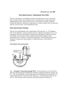
8 Operational AmplifiersTLT-8016 Basic Analog Circuits2005 Op-amp Imperfections in the Linear Range of OperationInput Impedance and Output ImpedanceInput impedance BJT input stage: > 100k , typically few M ; FET input stage: ~1012 Output impedance:~100 or the gain the Op Amp is high, the influence of the input and output impedance is nonideal characteristics of real op amps fall into three categories:1. Nonideal properties in the linear range of Nonlinear DC offsets. 2. Operational AmplifiersTLT-8016 Basic Analog Circuits2005/200615 Gain and Bandwidth Limitations When the Op Amp is included in a feedback loop in order to realise a finite gain amplifier , the bandwidth of the finite gain amplifier is extended proportionally to the Bode plot of open-loop gain for a typical op amp.
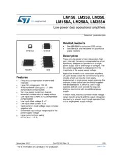
9 F/f(jA)f(ABOLOLOL+=10( )Figure Bode Operational AmplifiersTLT-8016 Basic Analog Circuits2005/200616 Some Popular Op AmpsTable Typical specifications for two popular Op AmpsType LM741 LF411A0OL 2 1052 s15V/ sInput resistance 2M 1012 Output resistance 50 50 Voff1mV 50pAIoff20nA 25pA 2. Operational AmplifiersTLT-8016 Basic Analog Circuits2005 Large Signal OperationOutput voltage SwingOutput Current LimitsFigure For a real op amp, clipping occurs if the output voltage reaches certain A741: If the supply voltages are +15V and 15V the amplitude of the output voltage without clipping is 14V typically (guaranteed is 12V).)
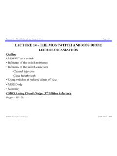
10 The maximum that an Op Amp can supply to a load is restricted. For A741 this limitation is 25mA. If a small-value load resistance drew a current outside this limits, the output waveforme would become Operational AmplifiersTLT-8016 Basic Analog Circuits2005/200618 Slew-Rate Limitations Slew-rate: the speed of the change of the output voltage . Maximum slew rate SR is limited for every Op dtdvo( )Figure An example of the effect of the slew-rate limitation on the output wave-shape in a certain finite gain amplifier , realized with Op Amp. 4vs(t) is the expected output wave shape based on the voltage gain. vo(t) is the real output wave-shape, distorted due to the limited slew rate of the Op Operational AmplifiersTLT-8016 Basic Analog Circuits2005 DC ImperfectionsDc currents flow into Op Amp inputs (they are the base currents of the input transistors).