Transcription of 2 – Orthographic Drawings
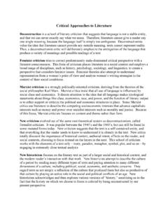
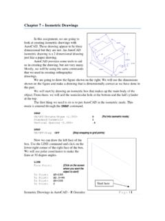
1 Orthographic Drawings in AutoCAD R GreenleePage | 1 2 orthographic drawings Orthographic Drawings are a very common style of drawing and are easily created with AutoCAD. In this exercise, we will use AutoCAD to draw the front, top, and right side views of the object shown at the right. We will start with a third angle view then try some first angle views in the exercises. The dimensions of the object are shown at the right and we will make our AutoCAD drawing dimensionally correct. Unlike some of our previous Drawings , we will use coordinates to draw the lines instead of simply clicking with the mouse. In the last assignment, you drew solid lines but sometimes you need dashed or dotted lines. AutoCAD has the ability to draw many different types of lines but the line type or style must be loaded before they can be used.
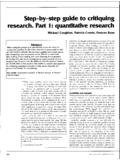
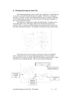
2 The line types are loaded with the commands: LINETYPE This brings up the line type dialog box shown on the right. Click on the LOAD button to bring up a selection of line types that can be loaded. The dialog box is shown on the right. Search through the file and click on the HIDDEN2 line type. We will use this line type to draw hidden lines in our Orthographic or multi-view Drawings . You can highlight several line types by holding down the CTRL key while you click on the names. Once you have selected the HIDDEN2 name, click on the OK button. We could load many other lines types but this is the only one we will need for this drawing. Now click on the LAYER PROPERTIES button shown in the figure shown on the right.
3 This button creates the layers management dialog box shown at the top of the next page. Load Button Manage Layers Hidden Line Orthographic Drawings in AutoCAD R GreenleePage | 2 Lines, circles, and arcs belong to layers and each layer determines how the lines, circles, and arcs will be drawn. The layer controls the color, line type, line weight and several other attributes for the layer. These attributes are: Layer Name The name used for the layer. Each layer has a unique name. On/Off If on the lines can be seen and if off they cannot be seen if it is on it can be seen. Frozen This attribute is very similar to On/Off. If a layer is frozen, it cannot be seen. Locked The lines in the layer cannot be deleted or modified.
4 Color Determines the color of the lines when they are displayed. Line Type Determines which line type is used to draw lines in this layer. They can be solid or dashed in many different ways. Line Weight This attribute controls how thick the line is when it is drawn on the screen and plotted. The varying thickness on the screen can be turned on and off using a button at the bottom of the main window. Create New Layer This button creates a new layer. After it is created you can change the attributes so that it meets your needs. Current Layer Click on one of the existing layers then click on the Current Layer check mark. All lines drawn from this point on will be in the layer marked as the Current Layer.
5 This will remain in effect until the current layer is changed again. This dialog box allows you to create new layers and define their attributes. Click on the Create New Layer button and create layers with the names: OBJ, PROJ, Create New Layer Layer Name Line Type Line Weight Color Locked Current Layer FrozenOn/Off Orthographic Drawings in AutoCAD R GreenleePage | 3 HIDE, FOLD, and CENTER. Click on the color for the projection layer and change its color. This will make it easier to distinguish projection lines form object lines. You can choose a different color for each layer if you desire. In this exercise, we will create several new layers. They are: OBJ This layer is used for line that make up the objects we are drawing.
6 HIDE This layer is used for hidden lines. CENTER This layer is used for centerlines. PROJ This layer is used for lines that project from one view to the next. They aid in the placement and size of the views. FOLD Orthographic views are created by projecting views to the faces of a projection box. The lines in this layer represent the edges of that box. For the HIDE layer, click on the Line Type and select hidden from the list of loaded line types. This is the line type we added when we loaded line types in a previous step. We did not have to load the line types during that step, we can load them now. Click on the line type for the CENTER layer and in the line type dialog box click on the LOAD button.
7 Now search for CENTER2 in the line types, click on it then click on OK to load the line type also. You can now select it for the CENTER layer. The lines drawn in each layer can have different weights. Click on the line weight for the OBJ layer and set the line weight to mm. When you have finished that, click on the line weight for FOLD and set the line weight to mm. We will use different line weights for the object lines and for the folding lines between views. All other layers will use the DEFAULT line weight which is the thinnest line the graphics device can produce. We are going to start drawing lines in the OBJ ( object ) layer so click on the OBJ name to highlight it then click on the green check mark at the top of the dialog box that selects the current layer.
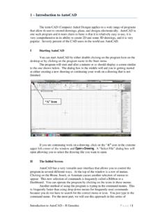
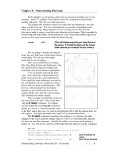
8 Once you have selected the OBJ layer, click on the X in the extreme upper left corner of the dialog box to dismiss the dialog box. Now we can start drawing the object . We will start with the Front view. Either type LINE or click on the line button at the top left of the Now use the LINE command to first draw the front view of the object . LINE From point: 1,1 {Start the drawing here for convenience} To point: To point: To point: @-2,0 To point: To point: Start here 1,1 @-2,0 Orthographic Drawings in AutoCAD R GreenleePage | 4 To point: C {Close the outline of the object } Next, draw the circle that represents the hole through the object . Note that you started the drawing at coordinates 1,1 so the center of the circle must be biased by these coordinates.
9 That puts the center at , CIRCLE 3P/2P/TTR/<Center Point>: , Diameter/<Radius>: D Diameter: 1 The finished drawing with the circle is shown above. This is the front view of the object . We set the OBJ layer lines to a line weight of mm but you will probably notice that they are not being drawn any heavier than any other line. We need to turn that feature on. At the bottom left of the screen, you will see a number of buttons which are shown in the figure below. These buttons help us control the drawing process. Click on the Line Weight button to turn on the display of heaver lines. ORTHO Mode Drawing perfectly horizontal and vertical lines with the mouse is very difficult, but AutoCAD can assist you.
10 At the very bottom of the AutoCAD window is a small icon shown above called ORTHO. ORTHO is an AutoCAD setting. When ORTHO is on, you can only draw vertical and horizontal lines with the mouse and when ORTHO is off, you can draw lines in any direction. You turn ORTHO on and off by clicking on the ORTHO icon at the bottom of the window or by typing the ORTHO command. When you click on the icon, the background of the icon changes colors indicating the ORTHO setting is on. You can turn the setting on and off while you are in the LINE or other commands by just clicking on the icon. The ORTHO setting does not affect lines drawn by entering coordinates. Snap Mode Grid Display Ortho Mode Line Weight object Snap Polar Tracking Absolute Coordinate , Orthographic Drawings in AutoCAD R Greenlee Page | 5 We will start the additions by drawing the folding lines.