Transcription of 8 – Working Drawings in AutoCAD
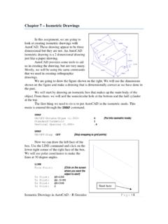
1 Assembly Drawings in AutoCAD R GreenleePage | 1 8 working drawings in autocad Most engineering designs consist of more than a single part. Usually there are a several or many parts that must fit and work together. When we are creating the Drawings of a design, we must create dimensioned Drawings of each part so that they can be manufactured correctly and we must also show how the parts fit together so they can be assembled correctly. The drawing of a single part is called a detailed drawing. It contains one or more orthographic views of the object, dimensions and possibly sectional and isometric views. In essence, a detailed drawing may contain all of the elements we have been studying this semester. An example of a detailed drawing is shown below. The drawing above shows two parts. Each part is shown in two different views, a front and a top view using a third angle projection. This is a detailed drawing of the two parts.
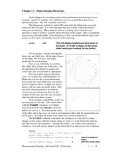
2 It contains sufficient information to build the parts. It does not tell us how to assemble the parts. That is shown in the drawing below. Bill of materials Balloons numbering the parts Exploded assembly view Assembled view Assembly Drawings in AutoCAD R Greenlee Page | 2 Note: The assembly views in the drawing above are shown as isometric or pictorial views. This is usually not done in AutoCAD Drawings . AutoCAD assembly views are usually orthographic because of the difficulty in drawing pictorial views. The Bill of Materials (BOM) lists all of the parts needed to make the machine. Each part is numbered in the BOM and the same number is used in the balloons that point to each part. The bill of materials lists the part number, the name of the part, and the material from which the part is made. Both exploded and unexploded assembly views are shown in this particular example but if the assembly can be fully explained with a single view, then only one view need be shown.
3 The view may be similar to one of the ones in the drawing above or it may be a sectional view. Sectional assembly views are especially useful if some parts are inside of housings or are concealed from view. A set of Working Drawings consists of a detailed drawing for each part that must be manufactured and sufficient assembly Drawings to explain how the parts are assembled. Detailed Drawings The first step in creating a set of Working Drawings is to create the detailed Drawings showing each part. Here you usually show a front view and possibly other views (top view, right side view, left side view, etc.) if they are required to fully describe the geometry. Sectional views and isometric views may also be included if the geometry is not easily understood from the orthographic projections. Dimensions are included on these Drawings so the part can be manufactured correctly. The title block on the drawing should contain the name of the part and this should be the same name used in the Bill of Materials.
4 After the detailed views are drawn, you can create the assembly Drawings . These Drawings are created by combining views from the detailed Drawings to show how the parts are assembled. The process involves several simple steps. 1. First you need to create the assembly drawing. You can do this by opening the Standard_A4 drawing sheet (You may have named it differently.) Once it is open, remember to use Save as to save the drawing under a different name. I usually use the abbreviation _ASM as the last characters in the file name so that I will know that this is an assembly drawing. 2. Open the detailed drawing to show the view of the part you want to insert into the assembly drawing. 3. Turn off all layers that are not needed in the view so that what is left can be easily selected. Dimensions and projection lines are not usually shown in assembly Drawings so these layers should be turned off. 4. Select the view you want to copy to the assembly drawing by dragging a box around it with the mouse.
5 Move the mouse to a location to the left and above the view and click. Next, move the mouse to a location to the right and below the view and click again. AutoCAD will select all of the objects in the view. Assembly Drawings in AutoCAD R GreenleePage | 3 5. Hold down the CTRL key and press the C key. This will copy everything you have selected to the program clipboard. 6. Next, you switch from the detailed drawing to the assembly drawing you are creating. You can do this by clicking on the big red A in the upper right corner and select the assembly drawing in the list of open files. 7. Paste the view from the detailed drawing into the assembly drawing by holding down the CTRL key and pressing the V key. Use the mouse to move the view to a convenient location then click to complete the copy. 8. Repeat this process for all of the parts in the assembly. When you have finished, you should have a drawing containing copies of all of the parts in the assembly.
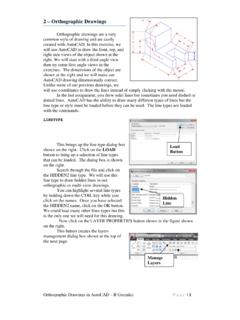
6 The figure below shows a bracket that is used to bolt two plates together. We will use this as an example. Building the Assembly After the parts have been copied to the assembly drawing, we can arrange them so that they are oriented correctly. We start by connecting Parts 4 and 5. Use the MOVE command to move Part 4 so that points A and B are at the same location. Point A is located at the intersection of the centerline and the bottom of Part 4 and point B is located at the intersection of the centerline and the top of Part 5. AutoCAD Selects Lines 1 Click here with mouse 2 Click here with mouse 1 2 34 5A BAssembly Drawings in AutoCAD R GreenleePage | 4 MOVE Select objects: w {Part 4 will be selected with a window} Specify first corner: {Click above and to the left of Part 4} Specify opposite corner: {Click below and t the right of Part 4} Select objects: {Press enter the selection is complete} Specify base point {Click on Point A at the intersection of the hole centerline and the bottom of Part 4} Specify second point {Click on Point B at the intersection of the hole centerline and the top of Part 5 The resulting placement is shown in the figure on the right.}
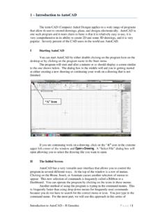
7 Next we will align point C with point D . Point C is located at the intersection of the centerline with the right side of Part 1. Point D is located at the intersection of the centerline and the left side of Part 4 as shown in the figure on the right. Here again, use the MOVE command to move Part 1 into the correct location. C DAssembly Drawings in AutoCAD R GreenleePage | 5 Next, create a copy of the bolt and insert the copy into the vertical hole. The copy is created with the COPY command as shown below. COPY Select objects: W {select the bolt with a window} Specify first corner: {click above and to the left of the bolt} Specify opposite corner: {click below and to the right of the bolt} Specify base point: {select a point on the bolt} Specify second point {select a point away from all other objects to place the bolt} Specify second point or [Exit/Undo] <Exit>: {press enter} The results of the copy are shown in the figure above.
8 The bolt on the right will be rotated 90 degrees clockwise and inserted into the hole. The first step is to rotate the bolt which is done with the ROTATE command. This command also requires that you select all of the objects to be rotates and you can again use the W option to create a selection window. When you rotate the bolt, be careful not to rotate it over another part. You can control the rotation by picking a base point (center of rotation) that is near the end of the bolt ROTATE Select objects: W Specify first corner: {click above and to the left of the bolt} Specify opposite corner: {click below and to the right of the bolt} Select objects: {press enter} Specify base point: {click near the bottom to keep the bolt from rotating over another part. In this case pick point 1} Specify rotation angle: -90 {the angle is negative because the rotation is clockwise} Now we insert the bolt into the vertical hole. Use the MOVE command and select a mid point on the bolt head (point 1) and the intersection of the centerline and the top of the hole (point 2) as the base point and the second point in the MOVE command.
9 MOVE Select objects: W Specify first corner: {upper left} Specify opposite corner: {lower right} Select objects: {press enter} Copy bolt to here Assembly Drawings in AutoCAD R GreenleePage | 6 Specify base point: mid {enter mid and select point 1} Specify second point: {let OSNAP find the intersection of the top of the hole and the centerline point 2} When you have finished, your drawing should resemble the one shown above on the right. Next copy the nut, rotate it -90 degrees, and place it on the bolt as shown in the figure at the right. You can use the COPY, ROTATE, and MOVE commands just as you did for the bolt. The resulting drawing is shown on the right. Some of the interior lines of the bolt, should be changed to hidden lines. You can make these changes with the CHANGE command. CHANGE {Select the lines that should be changed to the hidden layer} Select objects: 1 found Select objects: 1 found, 2 total Select objects: 1 found, 3 total Select objects: {press enter} Specify change point or [Properties] ]: P {we are changing the properties} Enter property to change [Color/Elev/LAyer/LType/.
10 : LA {we want to change the layer} Enter new layer name <Object>: hidden Enter property to change [Color/Elev/LAyer/LType/.. : {press enter} 1 2 Assembly Drawings in AutoCAD R GreenleePage | 7 The bolt with hidden lines with correct hidden lines is shown on the right. Continuing moving and rotating parts until the parts are fully assembled and your drawing looks like the one on the right. These lines were changed to HIDDENA ssembly Drawings in AutoCAD R GreenleePage | 8 Creating Balloons Next, we need to create the balloons that identify parts. Balloons are called leaders in AutoCAD and we must first define balloon style leaders before we can draw them. Start by typing: mleaderstyle This produces the dialog box on the right. Click on the New button to create a new leader style. 1. Enter Balloons for the name of the new leader style we are creating. 2. Mark the Annotative check box.]