Transcription of 2008 Special Design Provisions for Wind and Seismic C
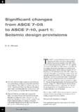
1 Updates and discussions related to codes and standartdsCodes and standardsSTRUCTURE magazineMarch 2010193" nominal - two lines of fastenersAdjoining panel edge3/8" " spacingBoundary fastening (two lines staggered is shown)2 1/2"1/2"1/2"2 1/2" - 3 1/2"Panel edge5 or 7 Equal Spaces2008 Special Design Provisions for Wind and SeismicBy Philip Line, , Bradford K. Douglas, , and Peter Mazikins, , shear strength and apparent shear stiffness values are provided in Table for each combination of nailing and sheathing Strength Reduction EquationFor Perforated Shear WallEquation has been added to SDPWS to provide more accurate results for perforated shear walls having open-ings of different heights within the wall length. Equation was the basis for tabulated shear capacity adjustment fac-tors in the current SDPWS; however, for tabulation purposes, all openings in the perforated shear wall were assumed to have a height equal to the maximum opening height.
2 Use of the equation will always provide values of the shear capacity adjustment factor that are equal to or greater than obtained from the and NailingFor Shear Walls Sheathed On Two SidesNew Provisions for staggering of ad-joining panel edges and minimum nominal framing width for two-sided wood structural panel shear walls (Figure 2) with nail spacing less than 6 inches on center are consistent with similar provi-sions in the 2006 IBC. Staggered nailing at adjoining panel edges where 3 inches nominal or wider framing is used is also added. This new provision appears under footnote 6 of Table and footnote 5 of Table Wall ConstructionTwo 2x Members as an Alternative to a Single 3x MemberUse of two 2x framing members ad-equately fastened together in place of a single 3x member required at adjoining panel edges in shear wall construction is consistent with guidance in the 2005 SDPWS Commentary, as well as a similar provision in the 2006 IBC.
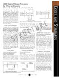
3 To address proper fabrication where nail spacing in the stitched members at adjoining panel edges is close, staggered nailing is required where fastener spacing is closer than 4 inches on Shear WallsNew Provisions for unblocked wood structural panel shear walls are applicable only to wood structural panel shear walls 16 feet in height or less, aspect ratio of 2:1 or less, and panel edge nail spacing of 6 inches on center. Unblocked shear wall adjustment factors, ranging in value from to , reduce the strength of the reference blocked shear wall with studs at 24 inches on center to account for presence of unblocked panel shear walls exhibit load-deflection behavior similar to that of the blocked shear wall reference condition but with reduced values of strength based on application of Cub. To account for reduction in unblocked shear wall Figure 1: Excerpt from SDPWS Figure 4C High load 2008 Edition of the Special De-sign Provisions for Wind and Seismic was approved as an American National Standard on August 4, 2008, with a des-ignation ANSI/AF&PA SDPWS-2008.
4 The 2008 SDPWS was developed by AF&PA s Wood Design Standards Com-mittee (WDSC) and contains Provisions for Design of wood members, fasteners, and assemblies to resist wind and Seismic forces. Several additions and revisions to the specification have been incorporated in this latest Load DiaphragmsProvisions for wood structural panel blocked diaphragms with multiple rows of fasteners, also known as high load dia-phragms , have been added consistent with Provisions in the 2006 International Build-ing Code (IBC) and the 2003 National Earthquake Hazard Reduction Program (NEHRP) Provisions . A distinguishing feature of high load diaphragms, rela-tive to typical blocked wood structural panel diaphragms, is use of nominal 3x or 4x framing at adjoining panel edges and boundaries and presence of multiple rows of fasteners at these locations (Figure 1).
5 Apparent shear stiffness values are tab-ulated for each combination of nailing and sheathing thickness as is done for typi-cal blocked and unblocked diaphragms in the SDPWS to simplify calculation of diaphragm WallsWood Structural Panels Installed Over Gypsum Wallboard or Gypsum Sheathing BoardProvisions for wood structural panels applied over gypsum wallboard or gypsum sheathing have been added consistent with Provisions in IBC and NEHRP. Adjoining panel edgea. Adjoining panel edges staggeredAdjoining panel edges staggeredAdjoining panel edgeAdjoining panel edgeb. Adjoining panel edges not staggered3x framingor blockingFigure 2: Wood structural panel sheathing on T R U C T U R E magazineCopyrightSTRUCTURE magazineMarch 2010 STRUCTURE magazine20 Panel edgeNail spacing at intermediateframing, 12" row of fasteners1/2"1/2"SpacingSpacingAlternait e nail spacingper Table or wall Design nail spacingPanel edge3/4"SpacingSingle row of fastenersSheathing edge at bottom plate(single row and double row of fasteners)Single row of fastenersPanel edge3/4"Sheathing edge at top plate(single row and double row of fasteners)Double row of fastenersPanel edge1/2"1/2"SpacingSpacingSpacingFigure 3.
6 Excerpt from SDPWS Figure 4G Panel , which is proportional to reduc-tion in strength, SDPWS specifies that deflection of unblocked shear walls is to be calculated from standard deflection equations using an amplified value of in-duced unit Uplift and Shear ResistanceWood Structural Panels Resisting Wind LoadsProvisions for wood structural panels de-signed to resist combined shear and uplift from wind have been added in Section and update similar Provisions first recog-nized in the Standard for Hurricane Resistant Construction, SSTD-10 in 1999. Tabulated values of nominal uplift capacity for various combinations of nailing schedules and panel type and thickness establish limits based on calculations in accordance with the National Design Specification (NDS ) for Wood Con-struction, 2005 and conditions verified by full-scale testing.
7 Allowable values of up-lift capacity are determined by dividing the nominal values by the allowable stress Design (ASD) reduction factor of options for use of wood structural panels to transfer tension forces within a story or between stories are provided. Figure 3 provides minimum distance from top and bottom edges of wood structural panels used to resist tension and spanning from the top plate to the bottom plate within a single Lath and Plaster WallsA new category of shear walls using gypsum lath, plain or perforated, has been added in Table to recognize increased unit shear capacity and stiffness of this wall type where vertical joints in the gypsum lath are staggered. Unit shear values are based on cyclic testing and consistent with a similar revision accepted in the 2007 Supplement to the 2006 AnchorageRevised Provisions for plate washer size and location are specified for anchoring of wall bottom plates.
8 Increase in washer size, from 2 -inch square in the 2005 SDPWS to 3-inch square in the 2008 SDPWS, makes washer size consistent with 2006 IBC and 2006 International Residential Code (IRC) and provides specific allowance for the slot to facilitate washer -inch distance from the washer edge to the sheathed edge (Figure 4) limits po-tential for cross grain bending, but is not required for low strength sheathing materials because bottom plate failure is not the failure limit state. For low strength materials, failure mechanisms include tear-out and slotting ( gypsum wallboard) of the sheathing, as well as fastener head pull-through. An exception to the plate washer requirement is provided based on testing and is applicable for walls having an aspect ratio less than 2:1, nomi-nal shear for Seismic not exceeding 980 plf (comparable to 7/16-inch OSB with 8d nails at 3 inches at panel edges) and where hold downs are sized to resist total overturning ne-glecting dead load stabilizing Aspect RatioAn increased aspect ratio for structural fi-berboard shear walls has been incorporated in Table based on strength and stiffness determined from cyclic testing.
9 A maximum aspect ratio of :1 is permitted but adjust-ment factors accounting for reduced strength and stiffness are applicable where the aspect ratio is greater than For Seismic Design , the aspect ratio reduction factor is based on analysis of reduced stiffness of high aspect ra-tio walls relative to the reference case (aspect ratio 1:1) and results in a maximum reduc-tion factor of at a :1 aspect ratio. For wind Design , the strength reduction factor accounts for observed reduction in peak unit shear strength as aspect ratio increases relative to the reference case and results in a reduction factor of at a :1 aspect revisions based on the testing pro-gram include an increase in the required panel edge distance for nailing at top and bottom plates and removal of 8d common nails as a permitted fastener for attachment of struc-tural fiberboard - Not Your Ordinary Fiber Wrap SystemIntroducing the Next Generation of FRP Advantages of SuperLaminate One size fits all Stronger than fiber wrap ISO-9000 certified plant Up to 80% faster construction time Material properties known before installationYou can learn more about these products by visiting Strengthening of concrete & masonry wallsRetrofit of beams, slabs & columns Repair of under-water piles with-out the need for costly divers Repair of columns below grade without the need for costly excavationTrenchless repair of pipes and culverts.
10 Including spot repairBlast retrofit of structuresField-manufac-tured cylindrical shell around square columns( )( )( )PLEASE CALL US FOR AN EVALUATION BY ONE OF OUR STRUCTURAL ENGINEERS (520) 791-7000 OR (866) QuakeWrap [782-5397] ADVERTISEMENT - For Advertiser Information, visit T R U C T U R E magazineCopyrightMarch 2010 STRUCTURE magazineMarch 201021 Sheathed edgeof bottom plate1/2" maximumPlate washer edgeADVERTISEMENT - For Advertiser Information, visit of Diaphragm and Shear Wall TablesWood Structural Panels (OSB and Plywood)A revised format of diaphragm and shear wall tables incorporates apparent shear stiff-ness, Ga, for OSB and plywood in the same tables. Previously, Appendix tables were used to provide tabulated values of apparent shear stiffness for DocumentsReferences to product standards have been updated.