Transcription of 2015 and LATER CHASSIS CAB AUXILIARY SWITCHES
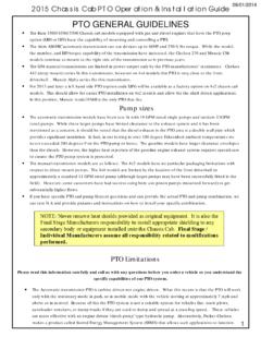
1 2015 and LATER CHASSIS CAB AUXILIARYSWITCHESC hassis Cab vehicles have 5 AUXILIARY SWITCHES . These SWITCHES are integrated into the vehicles electricalarchitecture (LIN signals) with their outputs found under hood in connectors located on the AUXILIARY PDC. Please notethat these SWITCHES are hard wired to only switch power (12V) via their relays; they cannot be used for suchapplications as PTO without upfitter modification. The vehicle comes with a kit 68209998AB that contains all requiredmating half terminals and connections to allow for ease of is a brief explanation of the switch operation:A) Non PTO Vehicle 5 SWITCHES located in the lower switch bank of the I/P all are AUXILIARY (AUX) All aux SWITCHES can be programed in the EVIC to be battery or ignition fed, momentary on, andsave last state Fuse sizes (rating) for the SWITCHES are customer choice via fuse relocations see the CHASSIS CabUpfitter Schematic for detailed instructions Connections to the SWITCHES are found under hood in the gray connectors attached to theauxiliary PDC.
2 See the CHASSIS Cab Upfitter Schematic for detailed instructions. The caps on the aux connectors are used in conjunction with the eight 12 AWG wires from theup fitter wiring kit to create the harness plug. Remove the green plug from the cap and insert1/4inch spade terminal on the wire into the cavity on the cap. It will click into place. AUX 5 power output is on the light gray connector under hood on circuit 2B) PTO Equipped Vehicle 5 SWITCHES located in the lower switch bank of the I/P 4 AUXILIARY (AUX) and 1 PTO All aux SWITCHES can be programed in the EVIC to be battery or ignition fed, momentary on, andsave last state. Fuse sizes (rating) for the SWITCHES are customer choice via fuse relocations see the CHASSIS CabUpfitter Schematic for detailed instructions Connections to the SWITCHES are found under hood in the gray connectors attached to theauxiliary PDC. See the CHASSIS Cab Upfitter Schematic for detailed instructions.
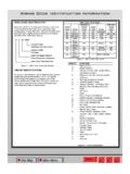
3 CHASSIS CAB HOME+- INDEX MAIN MENUALL IN OUTA U X I L I A R Y S W I T C H E SAux PDC Standard on all CHASSIS Cab Models Contains 8 fuses 5 - for the AUXILIARY SWITCHES (non-PTO vehicles)* 1 - for PTO and 4 for the AUXILIARY SWITCHES (PTO vehicle)* 1 - for 20 amp Upfitter battery feed 1 - for 20 amp Upfitter ignition/run feed 1 - 5 amp mini fuse can be customer located in its holder to allow changing SWITCHES 1 and 2 from ignitionfeed to battery feed** Houses 6 relays 5 - relays are for the AUXILIARY SWITCHES (non-PTO vehicle) 1 - relay is for PTO and 4 for the AUXILIARY SWITCHES (PTO vehicle) 1 - relay provides 20 amp Upfitter ignition feed*The 40A, 25A, and 20A AUX/PTO fuses can be moved as desired to any of the SWITCHES 1, 2, 3, 4 or 5 /PTO. These fuse sizes are for identification purposes only. Refer to the CHASSIS Cab Upfitter Schematic in theUpfitter Wiring Interface Instructions for max.
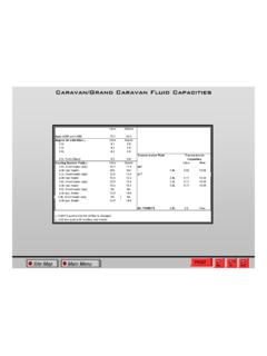
4 Allowable continuous amperage for a given fuse size .. INDEX MAIN MENU CHASSIS CAB HOMEALL INOUTAUXI LIARY SWI TCHES CHASSIS CAB HOME+- INDEX MAIN MENUALL IN OUTV ehicleSettings Au x programmableifveh ce iset:pipped antiPTO-Latching = stays active aiteirbutton press. Momentary = .xtrike only whenbuttoninheld down. Auic 4 Servings are centeal for al switchesxSwitches Enter PINP owerTake-OffSettingsPIN SetupPowSourceAux 3 Battery Ignition OnT y p e4,EVIC MessageOnly available for Power SortNoe-12nitian and Type - Latchindeemphasized ate-nil-se)Hold Last StateConditions Not MetPlease SeeOwner'sManualIfaVP2 orhigher 1:0 UCh5 Creenradio is equipped in the vehicle, 'Commercial Senings` will replace"Vehicle Settings-as the title to the settings main menu in the EVIC. The 'Commercial Settings-menu will only include Commercial settings ( , Aux SWITCHES , Power Take-Oft PIN Setup)CommercialAUX2PK/RDAUX4PK/TNAUX1PK /WTAUX3PK/DGNOCONNECTAUX5/PTOPK/VTCHASSI SGROUNDBKPassThroughVT/YL04/01/2014A U X I LI A R Y S W I TC H E SHere is the location of the connector with the switch outputs: CHASSIS CAB HOME+- I N D E X M A I N M E N UA L L I N O U T