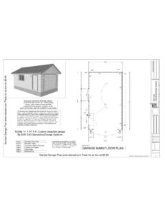
Transcription of 24' x 36' Gambrel Roof Cabin Plans E-Blueprints - SDSCAD
1 24' x 36' Gambrel Roof Cabin Plans E-Blueprints Gambrel Cabin Specifications 24 x 36 Main Floor 16 x 36 Loft 2 Bedrooms + Loft Sleep Area 1 Bath Plan sets contain the following:Plan sets contain the following: Floor Plans , Foundation Plans , Electrical Plans , Elevation Plans , Wall Framing Plans , Roof Framing Plans , Cabinet Details, Foundation Details, Wall section Details, Structural and General Notes, and Complete Building Materials Lists. 3046304630683046304630463046306830463046 2868286828685068D/WUPDN2x12 joists 16" OCDNDNSDSD4444'-6"3'-0"4'-6"10'-6"3'-0"1 0'-6"12'-0"24'-0"36'-0"2'-0"3'-0"10'-6"6 '-0"2'-6"15'-6"4'-6"3'-0"3'-0"3'-0"3'-0" 3'-0"4'-6"24'-0"4'-6"3'-0"6'-0"3'-0"4'-0 "3'-0"6"4'-6"3'-0"4'-6"24'-0"12'-0"36'-0 "Optional 12 x 24 Deck see detailsMicro Lam Beam5 1/2" x 14" MinGambrel Roof Cabin24' x 36'SDS-CAD specialized design email 2002 Main Floor PlanScale 3/16"=1'DN304630463046304628685068 SDSDBEDROOM13'-5" x 11'-2"36'-0"2'-6"3'-0"5'-0"3'-0"2'-6"4'- 0"16'-0"4'-0"24'-0"2'-6"3'-0"5'-0"3'-0"2 '-6"4'-0"16'-0"4'-0"24'-0"36'-0" Gambrel Roof Cabin24' x 36'SDS-CAD specialized design email 2002 Second Floor PlanScale 3/16"=1'36'-0"23'-9 3/4"12'-2
2 1/4"24'-0"24'-0"36'-0"12'-2 1/4"23'-9 3/4" Gambrel Roof Cabin24' x 36'SDS-CAD specialized design email 2002 Foundation Plan Scale 3/16"=1' Gambrel Roof Cabin24' x 36'SDS-CAD specialized design email 2002 Elevation ViewsScale 1/8"=1' Gambrel Roof Cabin24' x 36'SDS-CAD specialized design email 2002 Elevation ViewsScale 1/8"=1' Gambrel Roof Cabin24' x 36'SDS-CAD specialized design email 2002 Main Floor Framing2" x 6" Exterior Walls2" x 4" Divider Wall16" Base Plate Double Top Plate2" x 12" Joists 16" Door HeaderMin 2 - 2" x 12"Door and WindowHeadersMin 2" x 8"Main Beam to runThroughCenter of garageMin Size 5 1/2" X 14"Micro LamWith Max Span of 20' All Framing to be Doneasper UBC and LocalCodesFraming Details Scale 1/8"=1'Roof Framing LayoutScale 1/8"=1'24" " x 8" Rafters2" x 10" Ridge BoardSee Detail for moreInfoGambrel Roof Cabin24' x 36'SDS-CAD specialized design email 2002 See Foundation DetailsFor Concrete Spec2 x 12 Joist24/12 Pitch6/12 Pitch2 x 8 Ridge2 x 6 Rafters2 x 6 WallsGambrel Roof Cabin24' x 36'SDS-CAD specialized design email 2002 GeneralStucturalSectionsScale 3/16"=1'See GeneralSpecificationsfor DetailsGambrel Roof Cabin24' x 36'SDS-CAD specialized design email 2002 Stair Detail Scale 1/8"=1'Stair Width 36"Rise Max 8"Run 9" MinRailing Min 32" Max 36"Ballister Max Spacing 4"6' 8" Min Head Room36" x 36" Min Landing Top andBottom3- 2" x 12" StringersRailing Both Sides on Second FloorGambrel Roof
3 Cabin24' x 36'SDS-CAD specialized design email 2002with SIDING or STUCCOMONOLITHIC SLAB(2) #4 rebar footing 1'6 tall1'4 wide2" x 4" studs @ 16" oc& wind straps per anchor 3'6" ocsimpson or equalslope to drainfin. gradestuccoor 1/2" plywood# 15 felt on 1/2" cdx plywoodscratch coat on wire lath on R-max insulating sheathingor stucco finish coat on stucco1x8 horizontal hardboardlap sidingundisturbed soilcompacted fill(3000 psi)conc. footing6-6#10 mesh3000 psi, 4" batt insulation1/2" gypsum wall boardfinished floor level6 mil polyconc, slabcarpetbasesimpson or equal(2) #4 rebar anchor 3'6" oc& wind straps per codefin. gradeslope to drainfill R-max insulating sheathing2" x 4" studs @ 16" ocor 1/2" plywoodBrick vaneer6-6#10 meshfinished floor levelcompacted fillundisturbed soilMONOLITHIC SLAB with Brick Option1'4 widefooting 1'6 tallconc.
4 Footing(3000 psi)6 mil poly3000 psi, 4" " gypsum wall board optionalR-11 batt insulation optionalconc, slabbaseGambrel Roof Cabin24' x 36'SDS-CAD specialized design email 2002 RAISED SLAB with SIDING or STUCCO8"1'4"than 4 coursesfoundation wall is taller16" oc vert. wherehorizontal cmu wall tiescompacted fillon 6 mil barrier4" conc. slab w/ 6x6 #10 meshfloor finishbase1/2" gwb3000 psi conc. ftg.#4 bars, continuous#3 bars. 4' ocstuccoon site conditions# of blocks vary, depending8" cmu fill solid w/ conc.#4 bar 8' ocanchor, 3'-6" or eq. plate every 3rd studhurricane fasteners stud to2 x 4's 16" ocr-11 batt insulation7/16" osb boardsheathing or 1/2" plywoodCRAWL SPACE FOUNDATION with SIDING or STUCCO varies28102sheathing or 1/2" plywoodr-maxr-11 batt insulation2 x 4's 16" ochurricane fasteners stud tosill plate every 3rd stud248" cmu fill solid w/ conc.
5 # of blocks vary, dependingon site conditionsstucco#3 bars. 4' oc2 # 4 bars, continuous3000 psi conc. " gwbbasefloor finishhorizontal cmu wall ties16" oc vert. wherefoundation wall is tallerthan 4 courses1'4"8"wood or hardboard sidingor stucco finish coat on stuccoscratch coat on wire lath on# 15 felt on 1/2" cdx plywood(or per local code)provide sill plate anchorbolts, joist to footingstraps & stud to 2x10band wind ties per codewood or hardboard siding or stucco finish coat onstucco scratch coat onwire lath on # 15 felt on1/2" cdx plywoodr-19 batt insulationNOTES:- footings shown are for standard soil bearing capacities- install perimeter slabtreated sill with local codesheader blockGambrel Roof Cabin24' x 36'SDS-CAD specialized design email 20021/2" ANCHOR BOLT 6' BARRIER4" GRAVEL BASE4" CONCRETE SLABW/ WIRE MESH12" X 18" CONT.
6 CONCRETE FOOTINGREBAR (2) CONTINUOUS @ PERIMETERGRADE6" SLAB ON GRADEFOUNDATION - FROST (SLAB) - POURED CONC. " X 34"6"36"GRADE8" X 20" CONT. CONCRETE FOOTINGRE-BAR (2)8" POURED CONCRETE W/ VERTICAL REINF (IF REQUIRED)DAMP PROOFING (TO GRADE)1/2" ANCHOR BOLTS 6' BARRIER4" GRAVEL BASE4" CONCRETE FLOORW/ WIRE MESHS impsonStrong-TieHPAHD222 x EMBEDMENT LENTH + 12" MINIMUN REBAR 30" MINIMUMREBAR LENGTHCORNERDISTANCEFROM EDGEOF STRAP TOCORNERSINGLE POUR CORNERINSTALLATION12" MINIMUMREBAR LENGTHONE #4 REBAR INSHEAR CONEHPAHDS impsonStrong-TieFoundation details may varydepending on your local buildingconditions and codes. Consult acontractor or local buildingdepartment to ensure propertechniques for your areasbuilding DetailsDetails and SpecificationsCopyright 2001 SDSCAD E-Book Plans SDS - cad specialized design systems Web address Email: RAFTER TAILCONTINUOUS FASCIAFRIEZE BLOCKW/SCREENED VENTROOFING AND ROOFSHEATHINGSTUD WALL WITHSHEATHING AND FINISHTRIMALTERNATIVE FRIEZE BLOCKW/SCREENED VENT and Truss Detail2 Details and SpecificationsCopyright 2001 SDSCAD E-Book Plans SDS - cad specialized design systems Web address Email: " MINIMUMSIDECOVERSURFACE ASURFACE BOLT10" POURED CONCRETE.
7 (WITH TAPERED BOTTOM.)42"5/4" DECKING2" X 8" DECK JOIST2" X 6" TOP RAIL2" X 4" UNDER RAIL2" X 2" SPINDELS 5" Deck & Porch Detail Attatched to Wood WallCONCRETEFOUNDATIONGRADEFLOOR SYSTEMTREATED LEDGERNAILED TO SHEATHINGFLASHING TUCKED 1IN. UNDER SIDING ANDWRAPPED OVERLEDGER3/4" GALV. HOLLOWSPACERS FILLED W/SILICONE LAG BOLTSJOIST HANGERSDOUBLE TREATED BEAMWITH METAL BRACKETTREATED POST WITHMETAL POST PANOne Level Section, Truss Roof, Crawl Space2 - 2"X10" (CONTRACTOR TOVERIFY SIZE ANDCONNECTORS NEEDED)2"X4" KNEE WALL1" AIR SPACETYVEK HOUSE WRAPALUMINUM SOFFIT & FISCIA1" X 6' FASCIA (BACKER)INSULATIONEXT. PLYWOOD2"X FRAMING 16" "X BOTTOM PLATE2"X6" TREATED SILL PLATER44 INSULATION IN RIM JOIST 11 7/8" LPI FLOOR JOISTSANCHOR BOLTS (AS PER CODE)FOOTINGS WITH REEBAR(AS PER CODE)20' x 30' Aspen Cabin Copyright 2001 SDSCAD - Plan #472 E-Book Plans SDS - cad specialized design systems Web address Email: Western or Platform Framing Before any of the superstructure is erected, the first floor subflooring is put down making a platform on which the walls and partitions can be assembled and tilted into place.
8 The proc-ess is repeated for each story of the building. This framing system is used frequently. Firestopping All concealed spaces in framing, with the exception of areas around flues and chimneys, are to be fitted with 2 in. blocking arranged to prevent drafts between spaces. Exterior Wall Framing One-story buildings: 2 x 4's 16 in. or 24 in. ; 2 x 6's, 24 in. Two and three stories: 2 x 4's, 16 in ; 2 x 6's, 24 in. Bracing Exterior Walls Because floor framing and wall frames do no interlock, adequate sheathing must act as brac-ing and provide the necessary lateral resistance. Where required for additional stiffness or bracing, 1 x 4's may be let into outer face of studs at 45 angle secured at top, bottom, and to studs.
9 Bridging for Floor Joists May be omitted when flooring is nailed adequately to joist; however, where nominal depth-to-thickness ratio of joists exceeds 6, bridging would be installed at 8 ft 0 in. intervals. Building codes may allow omission of bridging under certain conditions. GENERAL NOTES:SOIL:CONCRETE: 1. FOUNDATIONS - 3000 @ 28 DAYS. TYPE II CONC. 5 BAG. 4. WALKS AND DRIVES - 3000 @ 28 DAYS, NO FLY ASH. 3. PROVIDE CONSTRUCTION JOINTS @ 400 SQ. FT. MAXIMUM. MIN. FTG. DEPTH PER DETAILS. 1. ALLOWABLE SOIL PRESSURE - 1500 MINIMUM WITH LOCAL CITY BUILDING CODES. SUB-CONTRACTORS PRIOR TO CONSTRUCTION. DRAWINGS. WRITTEN DIMENSIONS TAKE STEEL: CONC. TO BE 7".
10 #2 OR :LUMBER: 1. E70xx LOW HYDROGEN RODS 4. SEE DETAILS FOR 2. ROOF JOISTS, FLOOR JOISTS, BEAMS, LEDGERS AND PLATES TO BE DOUGLAS FIR 1. ALL SAWN LUMBER SHALL BEAR STAMP OF WWPA OR APPROVED TESTING AGENCY. ( APPROVED) TYPE WITH A 360 EXPANSIVE WEDGING ACTION. 3. ALL EXPANSION BOLTS TO BE "WEDGIT", RAM-SET, OR RED HEAD PHILLIPS LATEST AISC HANDBOOK. MIN. EMBEDMENT OF ALL BOLTS IN MASONRY, GROUT OR 2. BOLTS - ASTM A-307. LATEST AISC AND AWS CODES APPLY. ALL CONST. PER 1. ASTM A-36, Fy = 36 KSI, STRUCTURAL TUBES SHAL BE ASTM A-500 (Fy-46 KSI) 2. FLOOR SLABS - 3000 @ 28 DAYS. MAX. SLUMP = 3", NO FLY ASH 2. PROVIDE TERMITE PROTECTION OVER PER GOVERNMENTAL REGULATIONS.