Transcription of ø30 - IDEC Corporation
1 30 Series Control Units 30 30 Series Control Units (Selection Guide). Function Emergency Stop Switch Pushbutton Extended with Extended with Flush Extended Category Pushlock Turn Reset Half Shroud Full Shroud Momentary/Maintained Shape (Diecast) (Diecast) (Diecast) (Diecast). ABN1 ABN2 ABN2G ABN2F. Type HN1E ABD1 ABD2 ABGD2 ABFD2. AON1 AON2 AON2G AON2F. AOD1 AOD2 AOGD2 AOFD2. Page 6 13 69 13 69 13 69 13 69. Function Pushbutton Mushroom with Jumbo Mushroom with Jumbo Mushroom with Mushroom Palm Mushroom Category Full Shroud Shallow Shroud Deep Shroud Momentary/Maintained Momentary Shape (Diecast) (Diecast). ABN3 (Diecast) (Diecast) (Diecast). Type ABD3 ABN3G ABGD3 ABN4 ABN4G ABN4F. AON3 ABD4 ABGD4 ABFD4. AOD3 AOGD3. Page 14 70 14 70 14 70 14 70 14 70. Function Pushbutton Square Flush Square Extended Mushroom Pushlock Mushroom Pushlock Jumbo Mushroom Category Momentary Momentary Turn Reset Key Reset Pushlock Key Reset Shape (Diecast).
2 Type UBQN1 UBQN2 AVN3 ABN3K ABN4K. AVD3. Page 14 14 15 71 15 15. Function Pushbutton Mushroom Push Category Key ON/OFF Lock Toggle Lever Mushroom Pull Mushroom Push-Pull Turn Lock Shape (Diecast) (Diecast) ATN21 (Diecast). Type AJN3 ABN5 ATN4 ATN23. AJD3 AZD3 ATN22 AYD3. Page 15 71 15 15 16 71 16 71. 2. 30 Series Control Units (Selection Guide) 30. Function Pushbutton Twin Maintained Pushbutton Square Twin Square Twin Category Pin Lock Flush Mushroom Momentary Maintained Shape (Diecast). Type ABN8P UWQN1 UWQN2 ABBN11 ABBN33. ABD8P. Page 16 71 17 17 17 17. Function Pilot Light (LED) Pilot Light (Incandescent). Category Dome Square Rectangular (Marking) Dome (1W) Dome (2W). Shape (Diecast) (Diecast). APN1 UPQN4 (Diecast) APN1. Type APD1 UPQN3B APN1 APD1. APNE1 UPQNE4 APD1 APNE1. APDE1 APDE1. Page 18 72 19 19 19 72 18 72. Function Pilot Light (Incandescent) Illuminated Pushbutton (LED).
3 Extended with Rectangular (Marking) Dome Extended Category Square Flush (1W) Half Shroud (1W/2W). Push-to-Check Momentary/Maintained Shape ALN2 ALGN2. (Diecast). UPQN4 ALNE2 ALGNE2. Type UPQN3B APN1 P ALD2. UPQNE4 AOLN2 AOLGN2. AOLD2. AOLNE2 AOLGNE2. Page 19 19 21 22 73 24. Function Illuminated Pushbutton (LED) (Incandescent). Extended with Mushroom Mushroom Pushlock Mushroom Push Extended Category Full Shroud Turn Reset Turn Lock Momentary/Maintained Momentary/Maintained Shape ALFN2 ALN3 ALN. (Diecast) (Diecast) (Diecast) (Diecast). ALFNE2 ALNE3 AVLN3 ALNE. Type ALFD2 ALD3 AVLD3 AJLN3 ALD2. AOLFN2 AOLN3 AVLNE3 AOLN. AOLFD2 AOLD3 AVLDE3 AOLD2. AOLFNE2 AOLNE3 AOLNE. Page 26 74 28 75 31 76 31 23 73. 3. 30 30 Series Control Units (Selection Guide). Function Illuminated Pushbutton (Incandescent). Extended with Extended with Square Flush Rectangular Category Half Shroud Full Shroud Turn Lock Momentary Momentary/Maintained Momentary/Maintained Shape ALN F (Diecast).
4 ALN G ALNE3F3 ULQN ULQN B. Type ALFD2 ALN L. ALNE3G3 AOLN F UOLQN UOLQN B. AOLFD2. AOLNE3F3. Page 25 27 74 29 29 30. Function Illuminated Pushbutton (Incandescent) Selector Switch Mushroom Pushlock Mushroom Push Category Knob Lever Key Turn Reset Turn Lock Shape (Diecast). AVLN3 ASN (Diecast) ASN L (Diecast) ASN K (Diecast). Type AVLD3 AJLN3. AVLNE3 ASTN ASD ASTN L ASD L ASTN K ASD K. AVLDE3. Page 32 76 32 33/37 77 34/38 78 35/39 79. Illuminated Selector Illuminated Selector Function Selector Pushbutton Mono-Lever Switch Switch (LED) Switch (Incandescent). Category Knob Knob Ring Lever Standard Shape (Diecast) (Diecast) (Diecast) (Diecast) ARN. Type ASLN ASLN ABN ABN L. ASLD ASLD ASBD2 ASBD2L ARNS. Page 40 80 40 80 42 82 42 82 44. Function Mono-Lever Switch Cam Switch Maintained/. Category Interlocking Knob Key Spring Return Spring Return Shape ACSNO ACSNK. Type ARNL UCSQO UCSQM.
5 ACSSO ACSSK. Page 44 47 47 47 47. 4. 30 HN Series Emergency Stop Switches Emergency Stop Switches (Unibody Type) Speci cations Contact Ratings Speci cations Rated Insulation Voltage (Ui) 250V Operating 25 to +60 C (no freezing). Rated Thermal Current (Ith) 10A Temperature Illuminated units: 25 to +55 C. Rated Operational Voltage (Ue) 24V 110V 220V Storage Temperature 40 to +80 C. Resistive Load Operating Humidity 45 to 85% RH (no condensation). AC 6A 3A 3A. (AC-12) Contact Resistance 50 m maximum (initial value). 50/60. Hz Inductive Load Insulation Resistance 100 M minimum (500V DC megger). Rated 6A 3A 3A. (AC-15) Between live and dead metal parts Operational Current Resistive Load Dielectric Strength Contacts: 2,500V AC, 1 minute 6A 2A 1A. (DC-12) Illuminated parts: 1,000V AC, 1 minute DC. Inductive Load Damage limits: 60 m/s2. (DC-13) Vibration Resistance Operating extremes: 5 to 55 Hz, Note: The operational current represents the classi cation by amplitude mm making and breaking currents (IEC 60947-5-1).
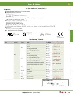
6 Damage limits: 1,000 m/s2. Minimum applicable load (reference value): 3V AC/DC, Shock Resistance Operating extremes: 100 m/s2. 5 mA (Applicable range may vary with operating condi- Operating Frequency 900 operations/h tions and load types.). Mechanical: 250,000 operations minimum Life Electrical: 100,000 operations minimum LED Lamp Ratings Degree of Protection IP65. Unit Rated LED Lamp Terminal Style screw Operating Rated Voltage Type No. Rated Voltage Current 24V AC/DC LSTD-2R 24V AC/DC 10% 10 mA. Applicable Standards and Approvals Safety Standards File No. or Organization UL508 UL Listing File No. E55996. Incandescent Lamp Ratings CSA No. 14 c-UL (File No. E55996). Unit Rated Incandescent Lamp EN60947-5-5 DEMKO approved Operating Voltage Type No. Wattage 24V AC/DC LS-3 1W (30V). Pushlock Turn Reset Switches (Unibody Type). Shape Contact Type No. Button Color 1NO-1NC HN1E-BV411R.
7 Red only 2NC HN1E-BV402R. When pressed , the button is held depressed. The button is released by turning clockwise. Terminal cover HW-VL7 is supplied with the switch. Illuminated Pushlock Turn Reset Switches (Unibody Type). Shape Lamp Contact Type No. Lens Color 1NO-1NC HN1E-LV411Q0R. Without Lamp Red only 2NC HN1E-LV402Q0R. When pressed , the button is held depressed. The button is released by turning clockwise. The illuminated pushlock turn reset switch does not contain a lamp. Order LED or incandescent lamps separately. For lamps, see page 63. Terminal cover HW-VL7 is supplied with the switch. 5. 30 HN Series Emergency Stop Switches Dimensions Panel Cut-Out HN1E-BV4. Terminal Screw Gasket Panel Thickness to 6 R0..8 m 3 ax. + 0. +0. 0 5. 33. Terminal Arrangement Locking Ring (Bottom View) 4. TOP Marking Side 0. 61. 63 32. HN1E-LV4. Terminal Screw Gasket Panel Thickness to 6.
8 Terminal Terminal Arrangement Screw (Bottom View) Lamp Terminal TOP Marking Side Locking Ring 4. X1 0. LAMP. X2 61 All dimensions in mm. 63 32. Replacement Parts Name Type No. Ordering Type No. Package Quantity Remarks Used on HN1E emergency stop switches for preventing Terminal Cover HW-VL7 HW-VL7PN10 10 electrical shocks. The HW-VL7 terminal cover is supplied with the HN1E. Nameplates Package Shape Type No. Legend Remarks Quantity Background: Yellow Legend: Black HNAV-0 (blank) Applicable panel thickness: to mm 60. Material: Polyamide 1 Legend EMERGENCY STOP . is indicated outside a 44mm 3. EMERGENCY circle. 0. HNAV-27 STOP. Accessory Package Shape Material Type No. Remarks Quantity Used for tightening the locking nut. Tighten the locking nut to a torque of to N m. Metal TWST-T1 1. 52. 77. 6. 30 30 Series Control Units Heavy duty control units offer both variety and reliability Endures harsh environments Degree of protection: IP65.
9 UL, CSA approved, and EN compliant. Safety Standards File No. or Organization UL Listing UL. File No. E68961. CSA File No. LR21451. EN EN60947-5-1. Speci cations and Ratings Contact Ratings Pushbuttons Contact Block Type BS/BST ( 30 series). Illuminated Pushbuttons Rated Insulation Voltage 600V. Selector Switches Rated Continuous Current 10A. Illuminated Selector Switches Contact Ratings by Utilization Category AC-15 (A600). Selector Pushbuttons IEC 60947-5-1 DC-13 (P600). Characteristics Contact Ratings by Utilization Category Operational Voltage 24V 48V 50V 110V 220V 440V. AC AC-12 Control of resistive loads and solid state loads 10A 10A 10A 6A 2A. Operational 50/60 Hz AC-15 Control of electromagnetic loads (> 72 VA) 10A 7A 5A 3A 1A. Current DC-12 Control of resistive loads and solid state loads 10A 5A . DC. DC-13 Control of electromagnets 5A 2A . Note: The operational current represents the classi cation by making and breaking currents (IEC 60947-5-1).
10 Minimum applicable load: 3V AC/DC, 5 mA (applicable range may vary with operating conditions and load types). For mono-levers and cam switches, see pages 43 and 46. BS (BST) Contact Block Contact Block Types Single-pole Contact Block Type Interlocking Groove Contact Mounting Terminal Screw Screw 1NO 1NC 1NO (early make) 1NC (late break). BS BS010E BS001E BS010SE BS001SE. Type BST BST010 BST001 BST010S BST001S. Push Rod Green Red Black White BST contact blocks are used for the following control units and are not interchangeable with BS contact blocks. (The BS housing is dark gray and the BST housing is light gray.). Pushlock turn reset and push turn lock switches LED illuminated pushbuttons Inspection Window Push Rod LED/incandescent illuminated selector switches All models of diecast zinc housing control units Durable nylon 66 housing has a high resistance against alkalis.