Transcription of 2945 INDICATOR POSTS - Kennedy Valve
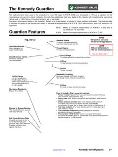
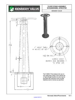
1 Kennedy VALVET elescoping post IndicatorWall PostISO 9000 ISO 14001 Telescoping post IndicatorFIELD ADJUSTMENT INSTRUCTIONS1. Remove the top section from the INDICATOR post Loosen the telescoping barrel screw and adjust barrel to the ground Cut the 1 square stem at a distance of 9 above the top of the barrel Set the OPEN and SHUT targets for the appropriate Valve Reattach the top section to the top of the INDICATOR post = 10"MIN. = 7"1" SQUARE STEM 9" TELESCOPING BARREL 2945A TRENCH DEPTH LIMITSB SIZEC SIZED SIZEE 31 51 49 69 67 87 88 111 6 35 55 53 73 71 91 92 115 8 42 62 60 80 78 98 99 122 10 45 65 63 83 81 101 102 125 12 49 69 67 87 85 105 106 129 14 58 78 76 96 94 114 115 138 2945 AUpdated 4/4/2014 INDICATOR post Parts ListPARTS LISTDETQTYPART WRENCHCAST IRON ASTM A126 CLASS BP-213024872 (4-14 )
2 OPERATING NUTBRONZE ASTM B584 ALLOY 864P-31442639 PRETAINER O-RING 226 BUNA NP-413020912 TOP SECTIONCAST IRON ASTM A126 CLASS BP-52441980 PWINDOW GLASSLEXAN-UV STABILIZEDP-62443370 POPEN TARGETCAST ALUMINUMP-72443371 PSHUT TARGETCAST ALUMINUMP-81-TARGET CARRIER ASSEMBLYP-8A13005802 (4-12 )TARGET CARRIER NUTBRONZE ASTM B584 ALLOY 864P-8B2443347 PTARGET CARRIER PLATE1/16 SHEET METALP-8C4440736 PCLAMP TARGET RETAINER16. GA 302 SSP-8D8444171P#10-24X1/2 PAN HEADZINC PLATED STEELP-8E4442411P#10-24 HEX NUTZINC PLATED STEELP-91443476P1/2 NPT PIPE PLUG MALL.
3 IRONP-101440254P3/8 EYEBOLT #23 FORGED STEELP-11A1444303P3/8-16X1 HEX CAPSCREW (ADJ. post )ZINC PLATED STEELP-121**STEM 1 SQUAREAISI M1020 HRSP-131318035&CRANE COUPLINGCAST IRON ASTM A126 CLASS BP-141442190 PCOTTER PINBRASSP-152444342P3/4 HEX HEAD SCREWZINC PLATED STEELP-1613004774 TELESCOPING BARREL5 Class 52 ANSI **LOWER STANDPIPE (ADJ. post )4 DI Class 52 ANSI (3-12 )BASE FLANGECAST IRON ASTM A126 CLASS BP-193444355P5/8 X1 HEX HEAD SCREWZINC PLATED STEELP-204444357P5/8 X2 1/4 HEX CAPSCREWZINC PLATED STEELP-214442484P5/8 HEX NUTZINC PLATED STEELU pdated 4/4/2014 Kennedy Valve / INDICATOR POSTS 17-7 INDICATOR POSTMODEL 2945A AND 2945 UL/FMINSTALLATION INSTRUCTIONS+%.
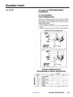
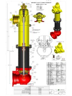
4 %$9 6!,6%Installation -4HE Valve SHOULD BE OPENED TO THE FULLY OPEN POSITION BEFORE PROCEEDING WITH THE )NDICATOR 0 OST INSTALLATION 1. Disassembly of the INDICATOR post Unit4 ELESCOPING "ARREL 5 NITS s 2 EMOVE THE 4OP 3 ECTION FROM THE END OF THE BARREL s ,OOSEN THE TWO SCREWS ON THE BARREL AND SLIDE OFF THE TOP OF THE STANDPIPE &IXED ,ENGTH 5 NITS s 2 EMOVE THE 4OP 3 ECTION FROM THE END OF THE STANDPIPE Flange Installation: s !TTACH THE BASE FLANGE ALONG WITH THE STANDPIPE TO THE Valve PLATE USING THE FOUR BOLTS AND NUTS PROVIDED 3.
5 Grade Line Adjustments:4 ELESCOPING "ARREL 5 NITS s ,OWER THE BARREL OVER THE STANDPIPE UNTIL THE GRADE LINE MARK ON THE BARREL IS AT GROUND LINE HEIGHT AND THEN TIGHTEN THE TWO SCREWS SECURELY &IXED ,ENGTH 5 NITS s #UT THE REQUIRED LENGTH OFF THE BOTTOM OF THE STANDPIPE SO THAT THE INDICATED GRADE LINE OF THE STANDPIPE IS AT THE GROUND LINE HEIGHT AND THEN SECURE TO THE BASE FLANGE BY TIGHTENING THE TWO SCREWS 4. Extension Rod Adjustments: ,OWER THE STEM INTO THE BARREL STANDPIPE PLACING THE CRANE COUPLING OVER THE Valve OPERATING NUT )T IS NECESSARY THAT THE STEM ENGAGE THE OPERATING NUT A MINIMUM OF INCHES BUT NOT MORE THAN INCHES 4O CHECK FOR CORRECT ENGAGEMENT THE END OF THE STEM SHOULD BE FROM INCHES TO INCHES ABOVE THE TOP OF THE STANDPIPE &IXED ,ENGTH 5 NITS OR THE TOP OF THE TELESCOPING BARREL 5.
6 Target (Open and Shut) Adjustments2 EMOVE THE TARGET ASSEMBLY FROM INSIDE THE BODY BY ROTATING THE OPERATING NUT COUNTERCLOCKWISE ,OOSEN THE TARGET RETAINER SCREWS BUT DO NOT REMOVE THEM Updated 05/02/2012 Updated 4/4/2014 17-8 Kennedy Valve / INDICATOR Posts5. Cont dOpen Left Valves-OVE THE /0%. TARGET TO THE TOP OF THE PLATE .OTE 0 OSITION OF THE 3(54 TARGET CAN BE DETERMINED BY THE FOLLOWING CHART 6 ALVE3 IZE 'ATE6 ALVE h!v 276 ALVE h!v 0 OSITION THE 3(54 TARGET AS INDICATED BELOW AND TIGHTEN THE RETAINER SCREWS UNTIL SNUG !))
7 VOID OVER TIGHTENING 2 EPEAT THE PROCEDURE FOR THE OTHER SIDE Open Right Valves4HE PROCEDURE IS SIMILAR AS FOR OPEN LEFT BUT WITH TWO DIFFERENCES ! 4HE OPEN TARGET IS PLACED below THE SHUT TARGET " 4HE OPEN TARGET IS PLACED AT THE VERY bottom OF THE PLATE 4HE POSITION OF THE SHUT TARGET ABOVE THE OPEN TARGET IS THEN DETERMINED AND SET AS DESCRIBED ABOVE Maintenance ,UBRICATIONL ubricate upper bearing area at least once per year, by applying several drops of light machine oil or food grade grease to the areas where the Operating Nut (P-2) contacts the Top Section (P-4).
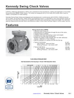
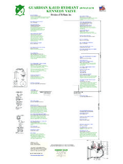
8 Access to this area is gained by removing the Locking Wrench (P-1) and lifting upward on the Operating Nut (P-2). /PERATION4HE TARGET MECHANISM WILL TRAVEL OFF THE THREADS OF THE OPERATING NUT IN BOTH DIRECTIONS SHOULD THE TARGETS OR TARGET MECHANISM BE POSITIONED INCORRECTLY 3 HOULD THIS HAPPEN READJUST TARGETS )F THE TARGET MECHANISM FALLS FROM THE OPERATING NUT IT WILL BE STOPPED A SHORT DISTANCE BELOW THE WINDOW INDICATOR POSTMODEL 2945A AND 2945 UL/FMINSTALLATION INSTRUCTIONS+%..%$9 6!,6%4561916 Valve size target location markingsAdjustment of target:1.
9 Grasp target at midpoint & pull out Slide up or down to desired location & then release grip. Updated 05/02/2012 Note (1): Resilient Seat Gate Valves 14" and larger, require special targetmechanism threads. Contact Kennedy Valve EngineeringSee Note (1)Updated 4/4/2014 Kennedy Valve / INDICATOR POSTS 17-92945 (A) Vertical INDICATOR post - Changing the Lower (2) 3/4" - UNC Bolts (Items P-15) that retain the Telescoping Barrel (Item P-16) to the lower Standpipe (Item P-17) in a safe manner lift off the entire top assembly (Items P-1 through P-16) from the Telescoping Barrel and Base the Stem (Item P-12) and Crane Coupling (Item P-13) the 3/4" -UNC Bolts 19)
10 That retain the Lower Standpipe to the Base the existing Lower Standpipe and set the new one into the socket in the Base tighten the bolts that were loosened in Step 4 (50 to 100 ) safely, slide the entire top assembly over the new Lower the (2) 3/4" - UNC Bolts that retain the Telescoping Barrel to the Lower Standpipe (Item P-15) - Tighten them securely enough to safely maneuver the post in the the Wrench (Item P-1), the 3/8" - UNC Bolt (Item 11A) and the Eyebolt (Item P-10) the assembly of the Top Section (Item P-4), Operating Nut (Item P-2), Target Carrier Assembly Items P-6 through P-8), etc.