Transcription of - 2D Meshing 2D Meshing - Altair University
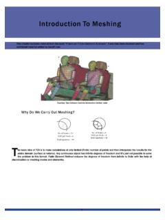
1 -2D Meshing -2D Meshing 2 DMeshing2 DMeshing2 DMeshing2 DMeshingThischapterincludesmaterialfromt hebook PracticalFiniteThischapterincludesmateri alfromthebook PracticalFiniteadditional material added by Matthias material added by Matthias geometry cleanup is completed ( surfaces are stitched nce geometry cleanup is completed ( surfaces are stitched geometry), Meshing is ), Meshing is rules of thumb when Meshing :Some rules of thumb when Meshing : Themeshshouldlook rathersmoothandregular(keep Themeshshouldlook rathersmoothandregular(keepquality is is key. Use the simplest element type suited for the problem. Use the simplest element type suited for the problem. Start with a coarse mesh and understand the modeling Start with a coarse mesh and understand the modeling Trytokeepmeshrelateduncertaintiestoamini mum ugly ugly , and how to use HyperMesh to create , and how to use HyperMesh to create are used when two of the dimensions are very large 2 Delements are used when two of the dimensions are very large t -thickness of platet -thickness of plateElement shape: Quad, triaElement shape: Quad, triaAdditional data from user: Remainingdimension thicknessAdditional data from user: Remainingdimension thicknessElement type: Thin shell, plate, membrane, plane stress, plane strain, Element type: Thin shell, plate, membrane, plane stress, plane strain, Practical applications: Sheet metal parts, plastic components like Practical applications.))
2 Sheet metal parts, plastic components like 112D Meshing -2D Meshing -FiniteElementAnalysis .Italsohasbeenreviewedandhas FiniteElementAnalysis .Italsohasbeenreviewedandhas stitched together no unwanted free surface edges inside thestitched together no unwanted free surface edges inside theeepinmindthattheanalysisisbasedonyour mesh andthemesheepinmindthattheanalysisisbase donyourmesh results; then use a finer mesh if results; then use a finer mesh if ,howtocreate2 Delementsofgoodonwhentouse2 Delements,howtocreate2 Delementsofgoodlarge incomparison to the third incomparison to the third , axi-symmetric solid etc. strain, axi-symmetric solid etc. e instrument panel instrument panel Meshing -2D Meshing Why Is 2D Meshing Carried Out On The Mid Surface?Quiteoftenthegeometryofthinwalle d3 Dstructures,asshownQuiteoftenthegeometry ofthinwalled3 Dstructures, (specifiedbytheuser)isassignedwithhalfth eelementthickness(specifiedbytheuser)isa ssignedwithhalfdirection(elementbottom).
3 Direction(elementbottom).Given 3D thin wGiven 3D thin wDerived mid-surDerived mid-surEnlarged view on the mid222D Meshing -2D Meshing -intheimagebelow,issimplifiedtoageometri cmodelwithlowerintheimagebelow, , , , ,halfinthe+Zdirection(elementtop)andtheo therhalfinthe Zhalfinthe+Zdirection(elementtop)andtheo therhalfinthe Zwalled geometrywalled geometryrface geometryrface geometrythe mid-surface model-2D Meshing -2D Meshing 2 DelementTriaTriaL(3)P(6)L(3)P(6)Alsoknow nasAlso known AlsoknownasConstantStrainAlso known LinearStrainTriangle (CST).LinearStrainTriangle(LSTriangle(LS *L Linear element *P Parabolic element*L Linear element *P Parabolic element*( ) Indicates number of nodes/element*( ) Indicates number of nodes/elementConstantStrainTriangle(CST) InformationConstantStrainTriangle(CST)In formationSome remarks regardingthe Constant Strain Triangle (CST) remarks regardingthe Constant Strain Triangle (CST) explanation below is taken from:The explanation below is taken from.))
4 The CST(Constant Strain Triangle) An insidious survivor from the The CST(Constant Strain Triangle) An insidious survivor from the TheCSTwasthefirstelement that wasdevelopedforfiniteelementTheCSTwasthe firstelement that wasdevelopedforfiniteelementIn the meantime, more accurate elements have been created and In the meantime, more accurate elements have been created and The ExplanationThe ExplanationConsider a 3-noded plane stress element inthe xy-plane withnode points 1 Consider a 3-noded plane stress element inthe xy-plane withnode points 13. The x-deflections are u1, u2, u3 and the y-deflections v1, v2 and The displacement function then has the followingform (usingsixconstants The displacement function then has the followingform (usingsixconstants The direct strains can then be calculated by differentiation:The direct strains can then be calculated by differentiation:332D Meshing -2D Meshing -elementshapesQuadQuadL(4)P(8)L(4)P(8)wn aswn asStrainStrainST)ST) infancy of FEA, by Prukl, MFTthe infancy of FEA, by Prukl, (thispaper is also uploaded to the Academic Blog).
5 PDF (thispaper is also uploaded to the Academic Blog)elementanalysis(FEA) (FEA) and these should be used to replace the and these should be used to replace the points 1, 2andnode points 1, 2andand v3, totalling six values to describe the behavior of the element):constants to describe the behavior of the element):i-2D Meshing -2D Meshing What Does This Mean? , , ,therefore, ,therefore, direct strains are then as follows:The direct strains are then as whichalso include the rotational degree of freedom about the elements whichalso include the rotational degree of freedom about the 442D Meshing -2D Meshing -r,thatinabeamwehavecompressionatthetopa ndtensionatr,thatinabeamwehavecompressio natthetopandtensionatmodellingbendingbeh aviorofabeam,itcannotmodelanythingatmode llingbendingbehaviorofabeam,itcannotmode lanythingatplanestressandstrainarequitea cceptable, ,platebendingandplanestressandstrainareq uiteacceptable, ,platebendinganddescribethebehaviorofthe element.
6 About the z-axis normal to the the z-axis normal to the Meshing -2D Meshing FamilyOf 2 DElementsFamilyOf 2 DElements1)PlaneStress1)PlaneStressDegre es of Freedom (DOFs) 2/node {U , U (in-planetranslations)}Degrees of Freedom (DOFs) 2/node {U , U (in-planetranslations)}xyStress in z direction (thickness) is zero ( =0)zStress in z direction (thickness) is zero ( =0)zUUyUxUxUyyUxUxzxPractical Applications: Thin sheet metal parts, like aircraft skin,narPractical Applications: Thin sheet metal parts, like aircraft skin,nar552D Meshing -2D Meshing -translations)}translations)}UUyUxUxUyTo tal dof = 8 UUxnarrow beamsnarrow beams-2D Meshing -2D Meshing 2)PlainStrain-DOFs 2/node{U , U (in-planetranslations)}2)PlainStrain-DOF s 2/node{U , U (in-planetranslations)}xyxyStrain in z direction (thickness) is zero ( =0)Strain in z direction (thickness) is zero ( =0)zUyyUxUyUyyUxzxUxzPractical Applications: Under ground pipes, wide beams, damsPractical Applications.
7 Under ground pipes, wide beams, damsPlane stress and plane strain elements are used for 2D(planner) Plane stress and plane strain elements are used for 2D(planner) 3)Plate-DOFs 3 / node{ , (inplane rotations) +U 3)Plate-DOFs 3 / node{ , (inplane rotations) +U xyz y xU xUz yTotal yU ,orstructuressuchasanalyzeobjectssuchasp ressurevessels, (exceptwhenaboutanaxisnormaltotheelement nodalmoments(exceptwhenaboutanaxisnormal totheelementgravity, , (thickness,elementnormalcoordinate,andel ementproperties(thickness,elementnormalc oordinate,itemsarebasedonthesurfacenumbe rofthelinesformingtheitemsarebasedonthes urfacenumberofthelinesformingtheonfourdi fferentsurfacenumbers,howtheseitemsareap pliedonfourdifferentsurfacenumbers,howth eseitemsareappliedthemesherfromaCADmodel orthe2 Dmeshgeneration),orwhthemesherfromaCADmo delorthe2 Dmeshgeneration), )Membrane-DOFs 3/node{U,U(inplanetranslations)+4)Membra ne-DOFs 3/node{U,U(inplanetranslations)+xyUyyUx zzUTotalUyTotalyUx yUx zzxzPractical Applications: Balloon, BafflesPractical Applications: Balloon, Baffles662D Meshing -2D Meshing -translations)}translations)}UyyUxUTotal dof=8 UyTotaldof=8 UxUx(planner) problems.}}
8 (planner) problems.(out of plane translation)}(out of plane translation)}z y xU xUz ytaldof = 12 , ,elementface),pressures(normaltotheeleme ntface),acceleration/elementface),pressu res(normaltotheelementface),acceleration /basedloads( pressure ,surfaceforce,andsoo n,butnotconstraints)basedloads( pressure , surfaceforce,andsoon,butnotconstraints)a ndsoon) ) ,andsinceeachelementcouldbecomposedoflin estheelement,andsinceeachelementcouldbec omposedoflinesdependonwhetherthemeshiscr eatedautomatically(byeitherdependonwheth erthemeshiscreatedautomatically( ssurfacenumberelementbasedontheelement ssurfacenumber+ (outofplanerotation)}+ (outofplanerotation)}zUyyUx zzUtaldof=12 Uytaldof=12Ux Ux z-2D Meshing -2D Meshing 5)ThinShell-Thin shell elements are the most general type of )ThinShell-Thin shell elements are the most general type of : 6 dof /node (U , U , U , , , ).DOFs: 6 dof /node (U , U , U , , , ).
9 XyzxyzThin Shell=Plate+MembraneThin Shell=Plate+Membrane(U , U , U , , , )=U , , +U , U (U , U , U , , , )=xyzxyzU , , zxy+U , U x=+(3T+3R)(1T+2R)(2T+1R)=+(3T+3R)(1T+2R) (2T+1R)U y yU y yU x xU x xU z zU U y yTotalU yU x xU z zzxz zzPractical Application: Thin shell elements are the most commonly used Practical Application: Thin shell elements are the most commonly used 6)AxisymmetricSolid-DOFs -2/node {U , U (2inplane translations, 6)AxisymmetricSolid-DOFs -2/node {U , U (2inplane translations, xzWhyistheword solid inthenameofa2 Delement?ThisisbecauseWhyistheword solid inthenameofa2 Delement? , , Applications: pressure vessels, objects of revolutions subjecPractical Applications: pressure vessels, objects of revolutions subjec772D Meshing -2D Meshing , U , , U , yz(2T+1R)(2T+1R)U y yU y yU x xU x xU z zU U y ytaldof = 24U U x xU z zz zmost commonly used commonly used translations, Z axis is axis of rotation)}plane translations, Z axis is axis of rotation)}becausethoughtheelementsarepla nner,theyactuallyrepresentbecausethought heelementsareplanner, , ,tationandacrosssection(planermesh).
10 The2 Dplanermeshistationandacrosssection(plan ermesh).The2 DplanermeshisUUyUUxUyTotaldof=8yTotaldof =8 Uxsubjected to axi-symmetric boundary conditionssubjected to axi-symmetric boundary conditions-2D Meshing -2D Meshing ThinShellElementsThinShellElementsThinSh ellElementsInthefollowingweinvestigateth e performance ofquadandtria-Inthefollowingweinvestigat ethe performance ofquadandtria-results are then compared witha given analytical are then compared witha given analytical 10mm AnalyticalAnswerAnalyticalAnswerThe Stress Concentration Factor (SCF) is defined as = max. stress The Stress Concentration Factor (SCF) is defined as = max. stress In this example the nominal stress is =F/A =10,000N/(1000mm*In this example the nominal stress is =F/A =10,000N/(1000mm*For an infinite plate SCF =3 For an infinite plate SCF =3 Hence, the maximum stress =Stress Concentration Factor (SCF) *Hence, the maximum stress =Stress Concentration Factor (SCF) *Inthe firstpartofthis study the effectsofelementtype(quad versusInthe firstpartofthis study the effectsofelementtype(quad versusglobal mesh size is mesh size is :thetranslationalTheboundaryconditionsfo rallmodelsarethesame:thetranslationaldeg reesoffreedom(x-,y-,z-displacements=0)of allnodesalongdegreesoffreedom(x-,y-,z-di splacements=0)ofallnodesalongleftedgeoft hemodelareconstrained(greensymbols)where asleftedgeofthemodelareconstrained(green symbols) ).)))