Transcription of 2D Triangular Elements
1 2D Triangular Elements Two dimensional FEA. Frequently, engineers need to compute the stresses and deformation in relatively thin plates or sheets of material and finite element analysis is ideal for this type of computations. We will look at the development of development of finite element scheme based on Triangular Elements in this chapter. We will follow basically the same path we used in developing the FEA techniques for trusses. In both cases, we developed an equation for potential energy and used that equation to develop a stiffness matrix. In the development of the truss equations, we started with Hook's law and developed the equation for potential energy.
2 F = k x ( ). Q. 1. u = k xdx = kQ 2 ( ). 0. 2. From here we developed linear algebraic equations describing the displacement of the nodes (end points) on the truss Elements to define a stiffness matrix c2 cs c 2 cs .. AE cs s 2 cs s 2 . k= ( ). L c 2 cs c 2 cs .. cs s s 2 . 2. cs We used this elementary stiffness matrix to create a global stiffness matrix and solve for the nodal displacements using KQ = F ( ). We are going to use a very similar development to create FEA equations for a two dimensional flat plate. Potential Energy The potential energy of a truss element (beam) is computed by integrating the force over the displacement of the element as shown in equation We will use the same idea but express it in a slightly different manner since we are not working with a one dimensional object such as a beam.
3 If we apply forces to a thin plate, the plate will deform and in the process store potential energy much the same way a spring will when an external force is applied. If we look at a small element of material in a plate that has been deformed, we can use the stress , to represent the force in the material and the strain , to represent the displacement of the material. The product of these can be integrated over the volume to Chapter 4 2D Triangular Elements Page 1 of 24. compute the potential energy due to external forces applied to the object. This is shown in the equation 1. U= V T dV ( ). 2. In we are integrating over the entire volume.
4 Since we are studying a flat plate of constant thickness, we can rewrite the equation as 1. U= A T tdA ( ). 2. where: is the strain in a differential element of the plate is the stress in a differential element of the plate t is the thickness of the plate (we assume it is a constant). A is the area of the plate In this equation, we are expressing the volume as the area of the plate times the thickness of the plate. We will use this equation for potential energy to develop the stiffness matrix for Triangular Elements in a thin plate. Our goal in this development is to replace both the stress and strain terms with linear equations for nodal displacement.
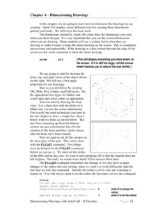
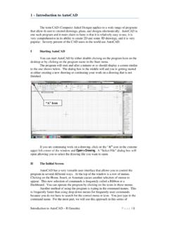
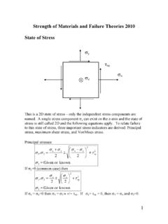
5 Equation involves both the stress and strain which we do not know. In the following development, we will eliminate both of these terms replacing them with the stiffness matrix and material properties. FEA Elements We can take a thin plate and divide it into triangles as shown in Figure 1 below. Point Force Node Element Fixed Boundary Figure 1 Triangular Elements used to approximate a flat plate. Chapter 4 2D Triangular Elements Page 2 of 24. The triangles share vertices with other triangles. The vertices are nodes and triangles are Elements . We will use the Elements and nodes to approximate the shape of the object and to compute the displacement of points inside the boundary of the object.
6 The object is fixed along part of the boundary and does not move. External forces are applied at points. These external forces may arise from simple point forces, tractions or forces applied along a length of the boundary, or body forces such as gravity. Regardless of the source, all forces are applied at the nodes only. Tractions, and body forces may be distributed across several nodes but they are still applied at the nodes. Two dimensional stress strain Relationship Previously we looked at using finite Elements to solve for the nodal displacements along a one dimensional truss member. We derived the equation = E ( ).
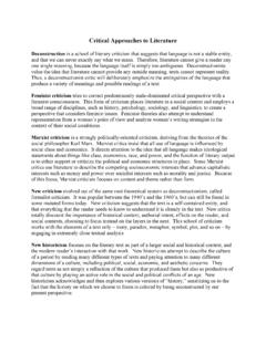
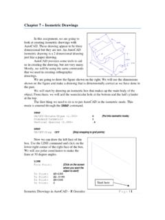
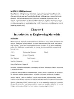
7 Where is the stress is the strain E is Young's modulus For the two dimensional case, this becomes a little more complex. If we look at a two dimensional element, we have y y xy xy X. X. xy xy y x Figure 2 Element showing both normal and shear stresses The stresses shown in the figure above can be used to write strain equations. Chapter 4 2D Triangular Elements Page 3 of 24. x y x = ( ). E E. y x y = ( ). E E. 2(1 + ). xy = xy ( ). E. Where: is the axial stress is the axial strain is the shear stress is the shear strain E is Young's modulus is Poisson's ratio We use the equations above to solve for the stress . First we solve for y resulting in y = E y + x ( ).
8 Substituting this into equation yields x (E y + x ). x = ( ). E E. or E x = x E y 2 x ( ). Solving for x gives us (1 2 ) ( x + y ). E. x = ( ). For the other equations (1 2 ) ( y + x ). E. y = ( ). and E. xy = xy ( ). 2(1 + ). We can write this in vector form as Chapter 4 2D Triangular Elements Page 4 of 24. 1 0 .. x E x ( ). = 1 0 . 1 1 . y 2 y .. 0 0 . 2 . xy xy or = D ( ). where 1 0 . E ( ). D= 1 0 . 1 1 . 2. 0 0. 2 . At this point, we are about half way to developing the stiffness matrix for the Triangular mesh. We can use equation to rewrite equation so that 1. U= A T tdA ( ). 2. becomes 1. U= A T D tdA ( ).
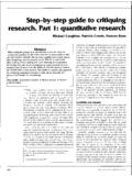
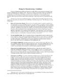
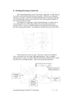
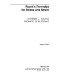
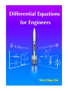
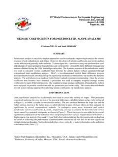
9 2. We have eliminated the stress term in the equation. We will go on from here to eliminate the strain term and develop the stiffness matrix. 2D Triangular Elements In the two dimensional truss problem, we computed the displacements of the nodes and we will do the same here. We will have displacements in the X and Y. directions and we will number them as shown in Figure 3. Q2 j Node j Q2 j 1. Figure 3 Diagram showing the numbering of nodal displacements. Chapter 4 2D Triangular Elements Page 5 of 24. For a single triangle we have q6. q5. q4. q2 q3. q1. Figure 4 Diagram of a triangle showing the numbering of the displacements of its nodes.
10 We can write the local displacement vectors for each triangle as q = {q1 q6 }. T. q2 q3 q4 q5 ( ). For the whole object the global vectors can be written as Q = {Q1 Q2 Q3 ..Qn }. T. ( ). Which includes all of the qn terms. Shape Functions We are going to compute the displacement of the nodes at the triangle vertices but we also need to compute the displacement for points inside the triangle. We will use shape functions to interpolate the nodal displacements to compute the displacements of arbitrary points inside the triangles. We will start by moving only one point on the triangle and holding the other two fixed.