Transcription of 3.0 ENGINEERING DESIGN, CONSTRUCTION, AND RIGHT-OF …
1 ENGINEERING design , construction , and RIGHT-OF -Way Acquisition Brookings County Hampton 3-1 December 2008 ENGINEERING design , construction , AND RIGHT-OF -WAY ACQUISITION TRANSMISSION LINE ENGINEERING AND OPERATIONAL design An HVTL consists of three phases, each at the end of a separate insulator string, all physically supported by structures. Each phase consists of one or more conductors. When more than one conductor is used to make up a phase, the term bundled conductors is used. Conductors are metal cables consisting of multiple strands of steel and aluminum wire wound together. There are also two shield wires strung above the electrical phases to prevent damage from lightning strikes. These cables are typically less than one inch in diameter. The shield wire can also include fiber optic cable that allows a path for substation protection equipment to communicate equipment at other terminals on the transmission line.
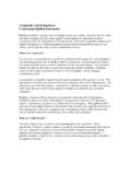
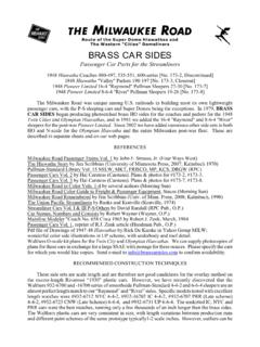
2 A double circuit transmission line carries two circuits or six phases and normally two shield wires. There are several different types of structures used for transmission lines, including single steel pole structures and H-frame structures. Transmission lines are constructed on a ROW, which is primarily dependent on structure design , span length and the electrical safety requirements associated with the transmission line s voltage. TRANSMISSION STRUCTURE design AND RIGHT-OF -WAY Transmission Structures The Applicants propose to use single pole, self-weathering steel double circuit structures for the majority of the Project (Figure 3-1). Self-weathering steel oxidizes or rusts to form a dark reddish brown surface coating to protect the structure from further weathering. Single steel pole structures are typically placed on a large concrete foundation. Each phase will consist of bundled conductors composed of two 954 ACSS cables or conductors of comparable capacity.
3 Each conductor is 954,000 circular mils or approximately inches in diameter. ACSS stands for Aluminum Conductor Steel Supported and consists of seven steel wires at the center surrounded by 54 aluminum strands. Applicants propose to use the same conductor and bundled configuration for all the 345 kV single circuit and double circuit transmission line sections. Specialty structures, including H-frame poles, may be required in certain limited circumstances. For example, H-frame structures are sometimes required near environmentally sensitive areas, including areas of significant bird activity. H-frames are also used for long spans in some instances. These structures consist of two wooden or steel poles with cross bracing. Concrete pier foundations may be used for angle structures or if soil conditions are poor. At the West Belle Plaine and Redwood River crossings, steel H-frame triple circuit structures may also be used.
4 For the Project 115 kV routes to connect the existing minnesota Valley New Ulm 115 kV transmission line with the new Cedar Mountain Substation, single pole wood or steel 115 kV horizontal post transmission lines would be constructed. Table 3-1 summarizes the structure designs and foundations for the single pole structures that will be used for the majority of the Project. Information about specialty structures, such as H-frames and triple-circuit, is also provided. ENGINEERING design , construction , and RIGHT-OF -Way Acquisition Brookings County Hampton 3-2 December 2008 Figure 3-1. 345 kV Double Circuit Single Pole Structure ENGINEERING design , construction , and RIGHT-OF -Way Acquisition Brookings County Hampton 3-3 December 2008 Table 3-1. Structure design Summary Line Type Structure Type Structure Material ROW Width (feet)a Structure Height (feet) Structure Base Diameter (inches) Foundation Diameter (feet)b Span Between Structures (feet) Pole to Pole Span on Single H-Frame Structure (feet) Single Pole Davit Arm Steel 150 130-175 36-48 (tangent structures) 48-72 (angle structures) 6-12 750-1,100 N/A 345 kV/ 345 kV Double Circuit H-Frame Steel 150-180 105-125 30-42 (tangent structures) 750-1,100 27 Wood 100 65-90 20-25 (tangent structures) N/A 300-400 N/A 115 kV Horizontal Post Steel 100 65-90 18-24 (tangent structures) 300-400 N/A 345/345/115 kV Triple Circuit H-Frame Steel 150-180 120-160 40-65 (tangent structures)
5 400-700 27 345/345/69 kV Triple Circuit H-Frame Steel 150-180 120-160 40-65 (tangent structures) 400-700 27 a ROW width depends on span length between structures. b It is unlikely that foundations will be used for H-frame structures as these poles are normally directly imbedded. Concrete foundations will only be used on an H-frame structure in special locations such as very poor soil conditions. The proposed transmission line and substations will be designed to meet or surpass all relevant local and State codes, NESC and NERC requirements and Applicant standards. Appropriate standards will be met for construction and installation and all applicable safety procedures will be followed during and after installation. RIGHT-OF -Way The majority of the new 345 kV transmission line facilities will be built with single pole structures, which typically require a 150-foot-wide ROW for the length of the transmission line.
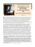
6 In some limited instances, where specialty structures are required for long spans or in environmentally sensitive areas, up to 180 feet of ROW may be needed for the transmission line. When the transmission line is placed cross-country across private land, an easement for the entire ROW (150 to 180 feet in width) will be acquired from the adjacent landowner(s). The Applicants will locate the poles as close to property division lines as reasonably possible. A diagram of a structure with ROW is shown in Figure design , construction , and RIGHT-OF -Way Acquisition Brookings County Hampton 3-4 December 2008 Figure 3-2. Double Circuit 345 kV Structure with ROW When the transmission line parallels other existing infrastructure ROW ( , roads, railroads, other utilities), an easement of lesser width may be required as parts of the ROW of the existing infrastructure can often be combined with the ROW needed for the transmission line.
7 When paralleling existing ROW, the Applicants typical practice is to place the poles on adjacent private property, a few feet off the existing ROW. With this pole placement, the transmission line shares the existing ROW, thereby reducing the size of the easement required from the private landowner. For example, if required ROW is 150 feet and the pole is placed five feet off of an existing road ROW, only an 80-foot easement would be required from the landowner and the additional 70 feet of the needed ROW would be shared with the road ROW. The arms on the pole would be approximately 85 feet above the ground depending on span length, and extend approximately 18 feet from the center of the pole. In each instance of sharing ROW, the Applicants will acquire necessary approvals from the ROW owner ( railroad) or the agency overseeing use of a particular ROW ( minnesota Department of Transportation ( MnDOT ) for State trunk highways, including Highways and Interstates.)
8 Throughout the route development process, the Applicants have sought to identify areas to share ROW with existing infrastructure, including transmission lines, highways and railroad ROW. This approach implements the State s policy of non-proliferation. In the context of transmission line siting, the non-proliferation policy creates a preference for placing new power lines near existing infrastructure as a way to minimize the proliferation of new corridors. The PPSA, minnesota Statutes Chapter 216E, and the Commission s implementing routing rules recognize this preference and call upon the Commission to consider the utilization of existing railroad and highway ROW as well as any existing transmission corridors in selecting transmission line routes. People for Envtl. ENGINEERING design , construction , and RIGHT-OF -Way Acquisition Brookings County Hampton 3-5 December 2008 Enlightenment and Responsibility (PEER), Inc.
9 V. minnesota Envtl. Quality Council, 266 858 (Minn. 1978). Among the potential ROW sharing opportunities identified for the Alternate Route is along Interstate 35. The Alternate Route parallels Interstate 35 for approximately seven miles between 57th Street West and the Lake Marion Substation area. MnDOT requires that a utility obtain a Utility Permit to construct transmission facilities along, across or in State trunk highways (interstate and non-interstate). Minn. Rule , Subp. 1. As a State agency that will need to issue a permit in connection with the construction of the transmission line, MnDOT must participate in the routing hearings and clearly state whether the proposed facility complies with State standards, rules and policies. Minn. Stat. Section , subd. 3. The Applicants have encouraged MnDOT s active participation in this process. Prior to filing this Application, the Applicants held several meetings with MnDOT representatives to discuss the proposed alignment of the transmission facilities adjacent to highways.
10 MnDOT representatives have expressed concern over the installation of the transmission line too near the road ROW along Interstate 35. Applicant Xcel Energy has also been meeting with MnDOT representatives as well as representatives from the Federal Highway Administration ( FHWA ) regarding the Fargo Twin Cities 345 kV project and the potential routing of transmission facilities along Interstate 94. MnDOT has advised the Applicants that any encroachment of the interstate ROW, including arm overhang or the swing of the conductors under extreme weather and line loading conditions, would require an exception to MnDOT policy, specifically MnDOT s Procedures for Accommodation of Utilities on Highway Right of Way (November 8, 2005) ( Accommodation Policy ). MnDOT has further stated that FHWA would need to concur for an exception to be granted to allow sharing of ROWs. The Applicants are continuing discussions with FHWA and MnDOT on these issues in an effort to clarify the situation.