Transcription of 3 Phase MegaPAC-ELTM (Low Noise) 4kW ... - Vicor …
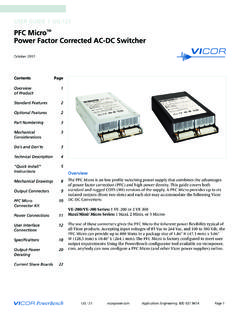
1 UG:108 Applications Engineering: 800 Page 13 Phase MegaPAC-ELTM ( low noise ) 4kW MegaPAC-ELTM (Low Noise) AC-DC SwitchersUSER GUIDE | UG:108 September 2013 Overview The 3 Phase megapac - EL and 4kW megapac - EL are field-configurable, single or multiple output switchers, providing up to 2,000 W (3 Phase megapac /EL- low noise ) to 4,000 W of output power (4kW megapac /EL- low noise ). The chassis has 10 slots and provides up to 20 regulated, fully isolated outputs. It achieves power densities of W per cubic inch (3 Phase megapac /EL ( low noise )) to W per cubic inch (4kW megapac /EL ( low noise ).)
2 The dimensions for the 3 Phase megapac /EL ( low noise ) are "H x "W x "L (124,5mm x 190,5mm x 429,3mm) and the dimensions for the 4kW megapac /EL ( low noise ) are "H x "W x "L (124,5mm x 190,5mm x 386,1mm). The 4kW megapac /EL ( low noise ) is longer than the 3 Phase megapac /EL ( low noise ) to accommodate a 2nd complete power supply is configured by selecting and inserting up to ten same length slide-in output assemblies called ConverterPACs. ConverterPACs incorporate one or two VI-200/VI-J00 and/or MaxiVicor DC to DC converters and are available in a wide selection of output voltage and power levels.
3 The net result is a power supply that offers the advantages of a custom supply, but is assembled from standard and modular building blocks. For detailed information about all ConverterPACs, refer to the ConverterPAC information sheets. The 4kW megapac -EL ( low noise ) uses VI-200/VI-J00 and Maxi Vicor DC to DC converters while the 3 Phase megapac -EL ( low noise ) uses VI-200/VI-J00 Vicor DC to DC at Vicor , the entire family of megapac power supplies is completely user-configurable. If output requirements change, , more power or a different output voltage is needed, upgrading is easy: simply unlock a single screw and replace the slide-in ConverterPAC with another Extended Length ConverterPAC that has the desired voltage power rating.
4 For additional flexibility, same length ConverterPACs can be connected in parallel to increase output power (booster ConverterPACs), or in series for higher voltages (total output voltage should not exceed 400 V). The driver is to the left of the boosters when looking at the output end of the supply. A user-friendly interface provides control and output sequencing capability, in addition to useful status indicators. Please consult our Applications Engineering Department if you have other special requirements. Contents Page Overview 1of Product Mechanical 2 Considerations megapac 3 Do s and Don ts Technical Description 4 Configuring and 5 Reconfiguring MegaPACs ConverterPAC 6 DescriptionPart Numbering 10 Quick Install 12 Instructions Mechanical Drawings 15 Interface Connections 17 Specifications 24 Current Share Boards 26 Low Leakage Version 29 SNRTLCUSCUS 3 Phase MegaPAC4kW MegaPACEnd of Life - Not Recommended for New Designs
5 UG:108 Applications Engineering: 800 Page 2 Standard Features n Input: 3 208/240 Vac Wye or Delta, 1 180-264 (47-500Hz) or 260 352 Vdcn Power Output: 3 Phase megapac : 2,000 W with 3 input; 1,200 W with 1 input 4kW megapac : 4,000 W with 3 input; 1,500 W with 1 inputn 10 slots (upto 20 outputs)n Fan cooled (4kW megapac -EL has 2 fans)n Full power to 45 C; half power to 65 Cn Power Factor Correction - passive - to PF (3 input)n Conducted EMI meets EN 55022 Level An AC Power OK and AC Power Fail status signalsn Output Sequencing and General Shutdown (Consult Applications Engineering for automatic sequencing circuitry.)
6 N Auto Sense capability Refer to page 12 and page 16 for more information on Autosensen Overcurrent protection on all outputsn Overtemperature limiting (not applicable with VI-J00)n Overvoltage protection (not applicable with VI-J00 modules)n Size: 3 Phase megapac - EL: "H x "W x "L (124,5mm x 190,5mm x 429,3mm) Extended chassis Size: 4kW megapac - EL: "H x "W x "L (124,5mm x 190,5mm x 386,1mm) Extended chassisn Safety Agency Approvals: cURus, cTUVus, CE MarkOptional Features n DC OK status signaln Output voltage adjustment range with built-in potentiometern Reversed fan airflow directionn Current Share Boards - see page 25 Mechanical ConsiderationsThe 3 Phase megapac - EL and 4kW megapac - EL can be mounted on any of four surfaces using standard 8-32 or 4mm screws.
7 The chassis comes with four mounting points on each surface; maximum allowable torque is 20 lb-in. The maximum penetration is in. (3,8mm).When selecting a mounting location and orientation, the unit should be positioned so air flow is not restricted. Maintain a 2" minimum clearance at both ends of the 3 Phase megapac - EL and 4kW megapac - EL and route all cables so airflow is not obstructed. The standard unit draws air in at the fan side/AC input side and exhausts air out the load side. If airflow ducting is used, use caution, as sharp turns could present back pressure to the 3 Phase megapac - EL and 4kW megapac - EL.
8 For the 4kW megapac - EL, the fans move approximately 50 CFM of air while for the 3 Phase megapac -EL, the fan moves approximately 30 CFM of air. The 4kW megapac - EL has a second fan for additional excessive bending of output power cables after they are connected to the 3 Phase megapac - EL or the 4kW megapac - EL. For high-current outputs, use cable ties to support heavy cables in order to minimize mechanical stress on output studs. Be careful not to short-out to neighboring output studs. The 3 Phase megapac - EL and UG:108 Applications Engineering: 800 Page 34kW megapac - EL are supplied with serrated, flanged hex-nuts on all output studs.
9 Therefore, thread locking compounds or lock washers are not required. The maximum torque recommended on flanged nuts is 45 lb-in. Never loosen the inner nut on a ConverterPAC. This nut supports the hardware inside the ConverterPAC and is factory applications in which the unit is exposed to excessive shock or vibration levels. In such applications, a shock absorption mounting design is required. megapac Do s and Don tsn For units without Autosense, do not leave ConverterPAC Sense lines open. Always terminate them to their respective outputs locally or at the load.
10 Use twisted pair 22-24 AWG wire. If ConverterPAC has Autosense, no local sense connection is required. See page 12 and 16 for more information on If needed, use Connector Kit # 19-130041 for the 3 Phase /4kW MegaPACs/EL - Low Always fill all output slots of the megapac . If a slot is not filled with a ConverterPAC, it should be filled with an airblock. Airblocks are plastic assemblies whose main function is to fill up an empty slot. Any airlfow escape from an empty slot significantly degrades thermal performance, and can result in overheating and damage to the power Do not unplug ConverterPACs while input power is applied.
