Transcription of 333 Breathing Systems in Anaesthesia
1 BASIC SCIENCE Tutorial 333. Breathing Systems in Anaesthesia Dr Peter Tsim Anaesthetic Trainee, Chesterfield Royal Hospital, UK. Dr Allan Howatson Consultant in Anaesthetics and Intensive Care Medicine, Nottingham University Hospital NHS Trust, UK. Edited by: Dr Alex Konstantatos Correspondence to 5th JULY 2016. QUESTIONS. Before continuing, try to answer the following questions. The answers can be found at the end of the article, together with an explanation. Please answer True or False: 1. When managing a 70kg spontaneously Breathing patient, the following fresh gas flows would be sufficient to prevent rebreathing: a. 6 litres per minute in a Mapleson A system b. 6 litres per minute in a Water's system c. 12 litres per minute in a Bain system d. 9 litres per minute in a Mapleson B system e. 9 litres per minute in a Ree's T-piece 2. Regarding Mapleson Breathing Systems : a.
2 The Bain system is a coaxial Mapleson A system b. The Mapleson D system is most efficient in ventilated patients c. A Mapleson C system has no adjustable pressure valve d. A Mapleson E (Ree's T-Piece) is suitable for use in patients up to 30kg e. The adjustable pressure valve requires a pressure of 1cm H2O to open it at its minimum setting 3. Regarding circle Systems : a. A high fresh gas flow rate is initially required to equilibrate the system b. The main component of soda lime is potassium hydroxide c. Compound A can be generated if low flow is used d. If the one-way valve becomes stuck, it leads to an increase in dead space in the system e. A closed circle system requires a lower fresh gas flow than a semi-closed system Key Points INTRODUCTION. The function of Breathing Systems is to deliver oxygen and Knowledge of anaesthetic Breathing anaesthetic gases to patients and eliminate carbon dioxide.
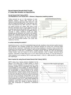
3 All Systems is essential for anaesthetists. Breathing Systems are composed of similar components but are configured differently. The common components include: fresh gas Different Breathing Systems show varying flow, tubing to direct gas flow, an adjustable pressure limiting valve efficiencies in spontaneously Breathing and to control pressure within the system & allow scavenging of waste ventilated patients. gas and a reservoir bag to store gas and assist with ventilation. Knowing the efficiencies of an individual Each Breathing system receives three sources of gas: fresh gas, Breathing system enables the user to exhaled dead space gas and exhaled gas from the alveoli. The deliver fresh gas to a patient in a way that proportions of each within the system are most greatly influenced minimises rebreathing of carbon dioxide. by fresh gas delivery.
4 Gas is delivered to spontaneously Breathing patients at sub-atmospheric (negative) pressure during inspiration Evaluating the performance of a Breathing and atmospheric pressure during exhalation. Conversely, ventilated system requires an understanding of the patients receive gas at positive pressure during inspiration and positioning of individual components as atmospheric pressure during exhalation. In this tutorial, we will well as the pressure changes during explore the different components and types of Breathing Systems spontaneous and controlled ventilation. used in common practice. Subscribe to ATOTW tutorials by visiting th ATOTW 333 Breathing Systems in Anaesthesia (5 July 2016) Page 1 of 6. COMPONENTS OF Breathing Systems . 1. A Breathing system is made up of components that connect the patient to the anaesthetic machine , and is usually composed of some or all of the following components: 1.
5 The Adjustable Pressure Limiting (APL) valve allows a variable pressure within the anaesthetic system using a one-way, spring-loaded valve. At a pressure above the opening pressure of the valve, a controlled leak of gas is allowed from the system , which enables control of the patient's airway pressure. The minimum pressure required to open the valve is 1cm H2O. A safety mechanism exists to prevent pressure from exceeding 60cm H2O, however, be aware that pressures below this can lead to barotrauma. 2. The reservoir bag allows collection of fresh gas flow during expiration, which in turn minimises the amount of fresh gas required to prevent rebreathing. In addition, it allows the anaesthetist to monitor the Breathing pattern of a spontaneously Breathing patient. These are usually plastic or rubber, and can come in sizes between litres to 6 litres.
6 However, the most common size in the adult system is 2 litres. Laplace's Law states that pressure is equal to twice the radius divided by the radius of the bag. Therefore, as the bag increases, the pressure within it reduces. This is an important safety measure as the expansion of the bag to accommodate gas limits pressure within the system . 3. The inspiratory limb allows passage of fresh gas flow to the patient for inspiration. The expiratory limb allows passage of expired gas from the patient. Although tubing length varies depending on the system in use, the diameter is of standard size: 22mm for adult and 18mm for paediatric Systems . MAPLESON CLASSIFICATION. In 1954, Prof William Mapleson published an article in the British Journal of Anaesthesia first describing the Mapleson 2. classification of Breathing Systems . Although named after him, the 5 semi-closed Systems which make up this 3.
7 Classification were first drawn by his colleague Dr William Mushin . FGF = fresh gas flow Volume of fresh gas flow to Mapleson RB = reservoir bag prevent rebreathing in Diagram spontaneously Breathing Classification APL = adjustable pressure limiting valve Pt = patient patients (multiples of MV). A. Macgill - Lack (coaxial). B - C. - Water's D. - Bain (coaxial). E. - Ayer's T-piece F. - Ree's T-piece Figure 1: The Mapleson Classification of Breathing circuits Subscribe to ATOTW tutorials by visiting th ATOTW 333 Breathing Systems in Anaesthesia (5 July 2016) Page 2 of 6. Mapleson A system This Breathing system consists of a reservoir bag at the anaesthetic machine and an APL valve at the patient end, separated by between 110-180cm of tubing. During the first breath, all gases inhaled are fresh and do not contain any exhaled gas. As the patient expires, the dead space gases are exhaled first.
8 As these have not undergone gas exchange, they contain the same gas mixture as was inhaled by the patient. These gases collect in the tubing. Meanwhile the fresh gas flow exiting the anaesthetic machine fills the remaining tubing and reservoir bag. As the pressure increases in the system and the patient continues to expire, the alveolar gases that have been used in gas exchange are forced to exit through the APL valve. As the patient takes the next breath, the dead space gases from the previous breath are inspired first, followed by fresh gas from the reservoir bag. The Mapleson A system is most efficient when used in spontaneously Breathing patients. In such cases, a fresh gas flow equivalent to minute volume is required as fresh gas can be accommodated in both the reservoir bag and the inspiratory limb tubing (550ml). However, if used for ventilated patients, the system is inefficient as the high pressure from the ventilator forces the fresh gas flow preferentially through the APL valve before the expired alveolar gas.
9 It therefore requires a much high fresh gas flow in order to prevent rebreathing. Due to the arrangement of the system , the weight and position of the APL valve at the patient end can be inconvenient. The co-axial system (Lack system ) has been developed for this: it features the expiratory limb tubing inside inspiratory limb and therefore has both APL valve and reservoir bag away from the patient while still maintaining the Mapleson A. arrangement. Mapleson B & C Systems The Mapleson B & C Systems are similar apart from the B system having tubing between the reservoir bag and the fresh gas flow, which further acts as a reservoir. As the APL valve is between the fresh gas flow and the patient, fresh gas that has not been involved in gas exchange is vented during expiration along with the expired gases in the spontaneously Breathing patient. A similar process happens when the patient is being ventilated: fresh gas is vented through the APL.
10 Valve before it can be delivered to the patient. Neither system is efficient for spontaneously Breathing or ventilated patients as to 2 times the minute volume is required to prevent rebreathing. Mapleson D system The Mapleson D system features the fresh gas flow being introduced at the patient end of the system . The APL valve and reservoir bag are at the anaesthetic machine end of the system and are separated from the patient by 180cm of tubing. An advantage of this is that all the heavy components are away from the patient. Mapleson D Systems are most efficient when used for ventilated patients. As the ventilator delivers the breath, the patient inspires gas from the fresh gas flow and reservoir. As the patient expires, the waste gas travels along the tubing and exits the system through the APL valve. During the expiratory pause, the fresh gas flow fills the tubing, further pushing the waste gas out through the APL valve.