Transcription of 39L Series - Carrier
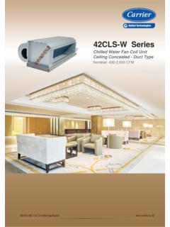
1 39l series Central Station Air Handlers Nominal: 2,000-17,750 CFM. World's Air Conditioning Expert 39l series Compact, fully-assembled air- handlers combine versatility with economical, dependable performance. Features & benefits Dependable performance The small footprint is easier to rig and ensures economical use of building space. The 39L is built to last. Sturdy milled galvanized steel formed panels ensure durability under all High efficiency fan minimizes air turbulence and climate conditions and operational wear. Double- avoids surging and unbalanced operation, cutting skinned access doors increase construction stability operating expenses. and provide low-frequency sound attenuation. Durable double-walled drain pan protects insulation from damage and controls moisture. Hinged access doors on most accessories facilitate service and maintenance, saving time and money. Internally mounted motors and drives are contained in a moving air environment where only cool, Flexibility filtered, dehumidified air circulates.
2 The result is Carrier offers a wide selection of coils for your 39L. longer motor bearing and belt life with less servicing. application. With the help of the Carrier Electronic In addition, factory-installed motors and drives are Catalog you can mix-match combinations of coils to protected from shipping damage and vandalism. All meet your application needs. factory-installed drives are aligned at the factory. And, factory-installed internally mounted motors and drives save installation time and expense. Chilled water coils The coil headers are constructed from schedule 40. Carrier precision balances all 39L fan wheels to limit steel pipe and are precisely sized to minimize water vibration and eliminate abnormal stress on bearings pressure loss. The coils are manufactured of 1/2-in. and other vital unit components. Rugged bearings OD copper tubes, aluminum or copper fins (either 8- are selected at a minimum 200,000 hours average or 14-fins per inch), and galvanized steel coil bearing life at maximum allowable operating casings.
3 They feature Carrier 's exclusive Opti-Fin . conditions. Bearings are securely fastened to a solid design for most efficient heat transfer. steel fan shaft with a split collet and clamp locking device. Field-proven bearings and fan shaft assure that vibration is controlled within narrowly prescribed Direct-expansion coils limits. Carrier 's direct expansion coils offer the advantage of design flexibility and total Units are designed to handle dehumidification optimization of coil performance. Coils are available operation at face velocities up to 550 fpm without in 4, 6 row with 8 or 14 fins (aluminum or copper). moisture carryover. per inch on 1/2-in. OD copper tubes. Choose from 2. or more circuitings on each coil surface for Economical maximum thermal performance with minimum refrigerant pressure drop. Liquid and suction Carrier 's 39L air-handlers are designed to save your connections are always on the same end, money. The units are shipped fully-assembled with a regardless of circuiting, and may be specified for single fan wheel and a single straight shot to the either right-or left-hand connections.
4 Ductwork. 2. Model number nomenclature 1 2 3 4 5 6 7 8 9 10 11 12 13 14 15 16 17 18 19 20 21 22 Digit Number 39L A 08 - 4/14 W - R - TF - 10 P F Standard Unit 39L D 08 - 4/14 W - R - UF - 10 P F Standard Unit Coil Circuit 39L - Light Commercial F - Full Circuit Air-Handler H - Half Circuit Unit Model A - Horizontal Draw Through Casing D - Vertical Draw Through P - Painted Galvanized Steel Unit Size Insulation 06, 08, 10, 12, 15, 18, 21, 25, 31, 35 15 - 15 MM Thick Fan Discharge Coil Row/Fin TF, UF, UR - For Unit Model A. 4/8, 4/14, 6/8, 6/14 UF, TF - For Unit Model D. Coil Type Hand W - Chilled Water Coil R - Right Hand Coil X - Direct Expansion Coil L - Left Hand Coil 39LA (Cooling). (UBR) (UBF). UPBLAST UPBLAST. REAR FRONT. K. G. (THF). TOP HORIZ. FRONT. Unit Arrangement Type Fan Discharge Type 39LD (Cooling). (UBR) (UBF). UPBLAST UPBLAST. REAR FRONT. K. G G. (THR) (THF). TOP HORIZ. TOP HORIZ. REAR FRONT. Unit Arrangement Type Fan Discharge Type 3.
5 Physical data (Chilled water coil). Description Light Commercial Air Handling Unit Model 39LA, 39LD. 06 08 10 12 15 18 21 25 31 35. Chilled Water Coil Nominal Performance* (1,000 Btu/h) Face Area sq. ft. 25** ** **. Number of Tube/Face 20 24 24 24 32 38 38 22/22 22/24 24/24. Finned Tube Length in. Connections Coil Connection in. MPT 1 1/2 2 1/2. Drain Connection in. MPT 1 1/2. Fans Nominal Capacity at 500 fpm CFM 2,950 3,950 4,770 5,600 7,450 8,850 10,800 12,500 15,450 17,750. Wheel Diameter in. 12 12 15 15 18 18 18 20 25 25. Fan Shaft Diameter mm. 25 25 25 25 25 25 25 35 45 45. Field Supplied Air Filters (in.) Motors Motor Type TEFC-Totally Enclosed Fan Cooled Motor Horsepower HP Depends on Air Flow and Static Pressure Nominal Motor Size HP Motor Shaft Diameter mm. Motor Full Load Amp Amp Approximate Motor Weight kgs Electrical Supply V/Ph/Hz 380/3/50. * Nominal performance are based on 45 F entering water, 10 F rise and 80/67 DB/WB entering air temp, 4R/14 F cooling coil.
6 Note : For more details in Performance Data, supplied with computer ** 39LA and 39LD units have 2 coils. selection, please contact your local area sales person. Approximate unit weight Model 39LA, 39LD. 06 08 10 12 15 18 21 25 31 35. Unit Type - Less Coil and Motor 39LA Less Coil and Motor kg 118 186 213 245 281 315 336 372 431 458. 39LD Less Coil and Motor kg 146 214 245 282 323 362 386 428 495 526. Chilled Water Coil Weight Dry Coil* 4-row kg 41 48 54 67 87 97 123 137 170 195. 6-row kg 47 61 69 86 116 133 162 180 223 256. Chilled Water Coil Volume 4-row litre 6-row litre Approximate Motor Weight HP kgs * Coils are 1/2 in. OD 14 Aluminium fins per inch on copper tubes, coil weight excluded water weight. 4. Chilled water coil connection position and diameter 80 80. OUT OUT. FILTER TRACK. FILTER TRACK. IN OUT. H H. G. IN J IN. F F. G I. DRAIN DRAIN. A A. B. B D. E. C C. 39LA, LD 06 to 21 39LA, LD 25 to 35. 39L Dimensions (mm.). Unit Size A B C D E F G H I J.
7 06 100 510 560 - - 37 230 550 - - 08 100 610 645 - - 37 235 645 - - 10 100 610 645 - - 37 235 645 - - 12 100 610 645 - - 37 235 645 - - 15 100 785 840 - - 37 235 815 - - 18 100 915 945 - - 37 235 955 - - 21 100 915 945 - - 37 235 955 - - 25 100 160 640 525 615 37 815 1250 165 600. 31 100 185 640 530 625 37 870 1250 165 600. 35 100 185 640 535 625 37 870 1350 165 600. Service area FAN/COIL. 2'-0". (610). A. 2'-2". D (660). COIL AREA B. C. FAN AREA. VERTICAL. DRAW-THRU Dimensions (mm.). 39L. Unit Size D. A B C. 39LA. 2'-0" 06 1162 1159 640 600. (610). 08 1262 1259 740 700. A 10 1462 1459 740 700. 12 1653 1659 740 700. 15 1653 1659 940 900. B 18 1653 1659 1040 1000. C 21 1962 1959 1040 1000. 25 1962 1959 1240 700. 31 2262 2259 1240 700. 35 2462 2459 1340 700. 5. 6. Fan performance Coil Total Static Pressure (in. wg.). Vel. Model Area CFM. FPM. sq. ft. RPM BHP RPM BHP RPM BHP RPM BHP RPM BHP RPM BHP RPM BHP RPM BHP RPM BHP RPM BHP. 06 350 2065 621 716 806 887 963 1035 1101 1163 1224 1281 400 2365 626 715 801 881 956 1026 1092 1154 1214 1272 450 2655 636 719 800 877 950 1019 1084 1146 1205 1263 500 2950 651 728 804 877 947 1014 1078 1139 1198 1254 550 3245 671 741 812 881 948 1013 1075 1134 1192 1247 08 350 2765 641 722 801 877 948 1017 1082 1143 1202 1259 400 3160 665 737 809 880 947 1013 1076 1135 1193 1249 450 3555 695 760 825 890 953 1015 1075 1131 1188 1242 500 3950 731 789 848 907 966 1023 1079 1133 1187 1240 550 4345 771 823 877 931 984 1038 1090 1141 1192 1242 10 350 3335 518 592 662 728 791 850 907 960 1012 1062 400 3816 529 597 662 725 785 842 896 948 998 1047 450 4293 544 607 668 727 783 838 890 940 989 1036 500 4770 563 621 678 733 786 838 888 936 983 1029 550 5247 584 638 691 743 794 843 890 936 981 1026 12 350 3920 532 598 663 725 784 840 895 946 996 1045 400 4480 551 612 671 729 784 837 889 938 986 1033 450 5040 574 630 685 738 790 840 889 936 982 1027 500
8 5600 601 652 703 753 801 848 894 938 982 1025 550 6160 631 678 725 772 817 861 904 946 988 1029 15 350 5215 447 508 567 622 674 723 769 894 854 894 400 5960 459 514 569 622 671 719 764 888 848 888 450 6705 475 525 576 625 672 718 762 883 844 883 500 7450 494 541 587 632 677 720 762 880 841 880 550 8195 517 559 602 644 685 726 766 879 842 879 Fan performance Coil Total Static Pressure (in. wg.). Vel. Model Area CFM. FPM. sq. ft. RPM BHP RPM BHP RPM BHP RPM BHP RPM BHP RPM BHP RPM BHP RPM BHP RPM BHP RPM BHP. 18 350 6195 463 517 571 622 671 718 763 805 847 886 400 7080 484 533 581 628 674 718 761 802 842 881 450 7965 510 553 597 640 682 724 764 803 841 879 500 8850 538 577 617 656 695 734 772 808 844 880 550 9735 569 605 641 677 713 748 784 990 852 886 21 350 7560 493 528 563 599 635 673 713 753 794 836 400 8640 534 566 597 627 658 689 722 754 788 823 450 9720 576 606 635 662 690 717 744 772 800 829 500 10800 619 648 675 701 726 751 775 799 824 849 550 11880 661 691 717 742 765 788 811 832 855 877 25 350 8750 432 469 506 544 581 619 657 694 731 768 400 10000 463 496 529 562 594 627 660 692 725 758 450 11250 495 526 556 586 615 644 673 701 730 760 500 12500 527 558 586 614 640 667 693 718 744 770 550 13750 560 590 618 644 669 693 717 740 764 788 31 350 10815 294 333 372 409 444 478 511 542 572 601 400 12360 303 338 373 407 440 472 503 533 562 590 450 13905 314 347 379 410 441 471 500 528 555 582 500 15450 327 357 387 416 444 472 499 526 552 578 550
9 16995 341 370 398 425 451 477 502 527 552 576 35 350 12425 303 339 374 407 440 472 503 533 562 590 400 14200 316 349 380 411 441 471 499 527 554 581 450 15975 332 361 390 419 446 474 500 526 552 577 500 17750 349 376 403 430 455 480 505 529 553 576 550 19525 366 393 418 443 466 490 513 535 557 580 7. Unit dimensions 39LA. (UBR) (UBF). UPBLAST UPBLAST. 1/4" REAR FRONT. 1 x 2" LG. SLOT. K. (32) (50). G. 11/2". (THF). (38). TOP HORIZ. FRONT. 13/16". (29) 23/8" (BHF). (60) BOTTOM HORIZ. VIEW A FRONT. SUSPENSION & LIFTING BRACKET. COIL LOC. 5 UPPER. COIL LOC. 5. LOWER F E. AIR. LEFT HAND. FLOW. FAN SECTION. MOTOR. 3" A. (75 mm.). 25, 31 & 35 UNIT SIZE. M. COIL LOC. 1 L E F G. ACCESS RIGHT HAND. DOOR FAN SECTION. AIR ON MOTOR (SEE ABOVE FOR ) D. FLOW END. J. C. MOTOR. TYP. H RH COIL. 3" 1/2". A B. (75 mm.) 1. 1 1/4" FPT CONDENSATE DRAIN SEE VIEW A. TYP. (38). SAME HAND AS COIL CONNECTION. 03 THRU 21 UNIT SIZE. Dimensions (mm.). Unit 39LA. A B C D E F G H J K L M.
10 06 1,240 1,160 715 344 395 260 60 697 560 580 445 35. 08 1,440 1,260 815 344 395 273 87 800 655 653 443 35. 10 1,440 1,460 815 405 470 302 59 800 649 680 654 50. 12 1,440 1,660 815 405 470 353 60 800 655 680 443 50. 15 1,840 1,660 1,015 483 559 300 89 1,000 860 851 445 60. 18 2,040 1,660 1,115 513 559 312 95 1,107 960 921 445 60. 21 2,040 1,960 1,115 565 565 508 120 1,107 960 920 445 60. 25 1,940 1,960 1,315 640 640 450 184 1,100 1,154 1,050 444 50. 31 1,940 2,240 1,415 800 800 520 45 1,100 1,252 1,290 444 60. 35 2,040 2,440 1,415 805 800 670 40 1,100 1,252 1,295 444 60. 8. Unit dimensions 39LD. (UBR) (UBF). UPBLAST UPBLAST. 1/4. 1 " x 2" LG. SLOT REAR FRONT. (32) (50) K. G G. 11/2". (38) (THR) (THF). TOP HORIZ. TOP HORIZ. 1 "3/16 REAR FRONT. (29) 23/8". (60) (BHR) (BHF). VIEW A BOTTOM HORIZ. BOTTOM HORIZ. SUSPENSION & LIFTING BRACKET REAR FRONT. F E. LEFT HAND. M. FAN SECTION L E F G. MOTOR RIGHT HAND. ACCESS FAN SECTION. DOOR D. (SEE AT LEFT FOR ).