Transcription of 3D3428 MONOLITHIC 8-BIT data PROGRAMMABLE DELAY …
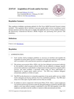
1 3D3428 MONOLITHIC 8-BIT PROGRAMMABLE DELAY LINE (SERIES 3D3428 LOW NOISE) FEATURES PACKAGES All-silicon, low-power CMOS technology CMOS compatible inputs and outputs Vapor phase, IR and wave solderable Auto-insertable (DIP pkg.) Leading- and trailing-edge accuracy PROGRAMMABLE via serial or parallel interface Increment range: through DELAY tolerance: (See Table 1) Supply current: 2mA typical Temperature stability: max (-40C to 85C) Vdd stability: max ( to ) FUNCTIONAL DESCRIPTION The 3D3428 device is a versatile 8-BIT PROGRAMMABLE MONOLITHIC DELAY line. The input (IN) is reproduced at the output (OUT) without inversion, shifted in time as per the user selection. DELAY values, programmed either via the serial or parallel interface, can be varied over 255 equal steps according to the formula: Ti,nom = Tinh + i * Tinc where i is the programmed address, Tinc is the DELAY increment (equal to the device dash number), and Tinh is the inherent (address zero) DELAY .
2 The device features both rising- and falling-edge accuracy. The all-CMOS 3D3428 integrated circuit has been designed as a reliable, economic alternative to hybrid TTL PROGRAMMABLE DELAY lines. It is offered in a standard 16-pin auto-insertable DIP and a surface mount 16-pin SOL. An 8-pin SOIC package is available for applications where the parallel interface is not needed. TABLE 1: PART NUMBER SPECIFICATIONS datadelaydevices, inc. 3 PIN DESCRIPTIONS IN Signal Input OUT Signal Output MD Mode Select AE Address Enable P0-P7 Parallel Data Input SC Serial Clock SI Serial Data Input SO Serial Data Output VDD + Volts GND Ground 12348765 INSOAEGNDVDDOUTSC SI 3D3428Z-xx SOIC143SO/P0MD 16151312111091245678 INAEP1P2P3P4 GNDVDD OUT P7 P6 SC P5 SI 3D3428 -xx DIP 12345678161514131211109IN AE SO/P0 P1 P2 P3 P4 GND VDDOUTMD P7 P6 SC P5 SI 3D3428S-xx SOL For mechanical dimensions, click here.
3 For package marking details, click here. PART DELAYS AND TOLERANCES INPUT RESTRICTIONS NUMBER Inherent DELAY (ns) DELAY Range (ns) DELAY Step (ns) Rec d Max Frequency Absolute Max Frequency Rec d Min Pulse Width Absolute Min Pulse Width MHz 77 MHz ns ns MHz 45 MHz ns ns 3D3428 -1 MHz 22 MHz ns ns MHz 15 MHz ns ns 3D3428 -2 781 KHz 11 MHz ns ns 625 KHz MHz ns ns 3D3428 -4 1020 390 KHz MHz ns ns 3D3428 -5 1275 312 KHz MHz ns ns 208 KHz MHz ns ns 3D3428 -10 10 2550 156 KHz MHz ns ns 3D3428 -15 15 3825 12 104 KHz MHz ns ns NOTES: Any DELAY increment between and 15 ns not shown is also available as standard. See application notes section for more details 2004 Data DELAY Devices Doc #04004 DATA DELAY DEVICES, INC.
4 15/8/2006 3 Mt. Prospect Ave. Clifton, NJ 07013 3D3428 APPLICATION NOTES The inherent DELAY error is the deviation of the inherent DELAY from its nominal value. It is limited to LSB or ns, whichever is greater. GENERAL INFORMATION The 8-BIT PROGRAMMABLE 3D3428 DELAY line architecture is comprised of a number of DELAY cells connected in series with their respective outputs multiplexed onto the DELAY Out pin (OUT) by the user-selected programming data (the address). Each DELAY cell produces at its output a replica of the signal present at its input, shifted in time. The change in DELAY from one address setting to the next is called the increment, or LSB. It is nominally equal to the device dash number. The minimum DELAY , achieved by setting the address to zero, is called the inherent DELAY . DELAY STABILITY The DELAY of CMOS integrated circuits is strongly dependent on power supply and temperature. The 3D3428 utilizes novel compensation circuitry to minimize the DELAY variations induced by fluctuations in power supply and/or temperature.
5 With regard to stability, the DELAY of the 3D3428 at a given address, i, can be split into two components: the inherent DELAY (T0) and the relative DELAY (Ti T0). These components exhibit very different stability coefficients, both of which must be considered in very critical applications. For best performance, it is essential that the power supply pin be adequately bypassed and filtered. In addition, the power bus should be of as low an impedance construction as possible. Power planes are preferred. Also, signal traces should be kept as short as possible. The thermal coefficient of the relative DELAY is limited to 250 PPM/C (except for the dash ), which is equivalent to a variation, over the -40C to 85C operating range, of ( 9% for the dash ) from the room-temperature DELAY settings. The thermal coefficient of the inherent DELAY is nominally +20ps/C for dash numbers 5 or less, and +30ps/C for all other dash numbers. DELAY ACCURACY There are a number of ways of characterizing the DELAY accuracy of a PROGRAMMABLE line.
6 The first is the differential nonlinearity (DNL), also referred to as the increment error. It is defined as the deviation of the increment at a given address from its nominal value. For most dash numbers, the DNL is within LSB at every address (see Table 1: DELAY Step). The power supply sensitivity of the relative DELAY is ( for the dash ) over the to operating range, with respect to the DELAY settings at the nominal power supply. This holds for all dash numbers. The sensitivity of the inherent DELAY is nominally 5ps/mV for all dash numbers. The integrated nonlinearity (INL) is determined by first constructing the least-squares best fit straight line through the DELAY -versus-address data. The INL is then the deviation of a given DELAY from this line. For all dash numbers, the INL is within LSB at every address. INPUT SIGNAL CHARACTERISTICS The frequency and/or pulse width (high or low) of operation may adversely impact the specified DELAY and increment accuracy of the particular device.
7 The reasons for the dependency of the output DELAY accuracy on the input signal characteristics are varied and complex. Therefore a recommended maximum and an absolute maximum operating input frequency and a recommended minimum and an absolute minimum operating pulse width have been specified. The relative error is defined as follows: erel = (Ti T0) i * Tinc where i is the address, Ti is the measured DELAY at the i th address, T0 is the measured inherent DELAY , and Tinc is the nominal increment. It is very similar to the INL, but simpler to calculate. For most dash numbers, the relative error is less than LSB at every address (see Table 1: DELAY Range). OPERATING FREQUENCY The absolute error is defined as follows: The absolute maximum operating frequency specification, tabulated in Table 1, determines the highest frequency of the DELAY line input signal that can be reproduced, shifted in time at the device output, with acceptable duty cycle eabs = Ti (Tinh + i * Tinc) where Tinh is the nominal inherent DELAY .
8 The absolute error is limited to LSB or ns, whichever is greater, at every address. Doc #04004 DATA DELAY DEVICES, INC. 25/8/2006 Tel: 973-773-2299 Fax: 973-773-9672 3D3428 APPLICATION NOTES (CONT D) distortion. Exceeding this limit will generally result in no signal output. The recommended maximum operating frequency specification determines the highest frequency of the DELAY line input signal for which the output DELAY accuracy is guaranteed. Exceeding this limit (while remaining within the absolute limit) may cause some delays to shift with respect to their values at low frequency. The amount of DELAY shift will depend on the degree to which the limit is exceeded. To guarantee (if possible) the Table 1 DELAY accuracy for input frequencies higher than the recommended maximum frequency, the 3D3428 must be tested at the user operating frequency. In this case, to facilitate production and device identification, the part number will include a custom reference designator identifying the intended frequency of operation.
9 The programmed DELAY accuracy of the device is guaranteed, therefore, only at the user specified input frequency. Small input frequency variation about the selected frequency will only marginally impact the programmed DELAY accuracy, if at all. Contact the factory for details. OPERATING PULSE WIDTH The absolute minimum operating pulse width (high or low) specification, tabulated in Table 1, determines the smallest pulse width of the DELAY line input signal that can be reproduced, shifted in time at the device output, with acceptable pulse width distortion. Exceeding this limit will generally result in no signal output. The recommended minimum operating pulse width (high or low) specification determines the smallest pulse width of the DELAY line input signal for which the output DELAY accuracy tabulated in Table 1 is guaranteed. Exceeding this limit (while remaining within the absolute limit) may cause some delays to shift with respect to their values at long pulse width.
10 The amount of DELAY shift will depend on the degree to which the limit is exceeded. To guarantee the Table 1 DELAY accuracy for input pulse width smaller than the recommended minimum operating pulse width, the 3D3428 must be tested at the user operating pulse width. In this case, to facilitate production and device identification, the part number will include a custom reference designator identifying the intended frequency and duty cycle of operation. The programmed DELAY accuracy of the device is guaranteed, therefore, only for the user specified input characteristics. Small input pulse width variation about the selected pulse width will only marginally impact the programmed DELAY accuracy, if at all. PROGRAMMED DELAY UPDATE A DELAY line is a memory device. It stores information present at the input for a time equal to the DELAY setting before presenting it at the output with minimal distortion. The 3D3428 8-BIT PROGRAMMABLE DELAY line can be represented by 256 serially connected DELAY elements (individually addressed by the programming data), each capable of storing data for a time equal to the device increment (step time).