Transcription of 4-20mA Current Loop Primer - PAControl.com
1 DMS APPLICATION NOTEI ntroductionThis application note s primary goal is to provide an easy-to-understand Primer for users who are not familiar with 4-20mAcurrent- loops and their applications. Some of the many topicsdiscussed include: why, and where, 4- 20ma Current loops are used;the functions of the four components found in a typical application;the electrical terminology and basic theory needed to understandcurrent loop operation. Users looking for product-specific informationand/or typical wiring diagrams for DATEL s 4- 20ma loop- and locally-powered process monitors are referred to DMS Application Note 21,titled Transmitter Types and Loop Configurations.
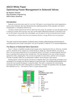
2 Despite the fact that the currents (4- 20ma ) and voltages (+12 to+24V) present in a typical Current loop application are relatively low,please keep in mind that all local and national wiring codes, alongwith any applicable safety regulations, must be observed. Also, thisapplication note is intended to be used as a supplement to allpertinent equipment-manufacturers published data sheets, includingthe sensor/transducer, the transmitter, the loop power supply, andthe display Use a Current Loop?The 4- 20ma Current loop shown in Figure 1 is a commonmethod of transmitting sensor information in many industrialprocess-monitoring applications.
3 A sensor is a device used tomeasure physical parameters such as temperature, pressure,speed, liquid flow rates, etc. Transmitting sensor information via a4- 20ma Current Loop PrimerFigure 1. Typical Components Used in a Loop Powered ApplicationTRANSMITTER SENSOR+ +POWER SUPPLYPROCESS MONITOR/CONTROLLER+ + 4-20mADATEL, Inc., Mansfield, MA 02048 (USA) Tel: (508)339-3000, (800)233-2765 Fax: (508)339-6356 Email: Internet: makes no representation that the use of its products in the circuits described herein, or the use of other technical information contained herein, will not infringe upon existing or future patent rights.
4 The descriptions containedherein do not imply the granting of licenses to make, use, or sell equipment constructed in accordance therewith. Specifications are subject to change without notice. The DATEL logo is a registered DATEL, Inc. loop is particularly useful when the information has to besent to a remote location over long distances (1000 feet, or more).The loop s operation is straightforward: a sensor s output voltage isfirst converted to a proportional Current , with 4mA normallyrepresenting the sensor s zero-level output, and 20ma representingthe sensor s full-scale output.
5 Then, a receiver at the remote endconverts the 4- 20ma Current back into a voltage which in turn canbe further processed by a computer or display , transmitting a sensor s output as a voltage over longdistances has several drawbacks. Unless very high input-impedancedevices are used, transmitting voltages over long distancesproduces correspondingly lower voltages at the receiving end due towiring and interconnect resistances. However, high-impedanceinstruments can be sensitive to noise pickup since the lengthysignal-carrying wires often run in close proximity to other electrically-noisy system wiring.
6 Shielded wires can be used to minimize noisepickup, but their high cost may be prohibitive when long distancesare a Current over long distances produces voltage lossesproportional to the wiring s length. However, these voltage losses also known as loop drops do not reduce the 4- 20ma Current aslong as the transmitter and loop supply can compensate for thesedrops. The magnitude of the Current in the loop is not affected byvoltage drops in the system wiring since all of the Current ( ,electrons) originating at the negative (-) terminal of the loop powersupply has to return back to its positive (+) terminal fortunately,electrons cannot easily jump out of wires!
7 , Inc., Mansfield, MA 02048 (USA) Tel: (508)339-3000, (800)233-2765 Fax: (508)339-6356 Email: Internet: makes no representation that the use of its products in the circuits described herein, or the use of other technical information contained herein, will not infringe upon existing or future patent rights. The descriptions containedherein do not imply the granting of licenses to make, use, or sell equipment constructed in accordance therewith. Specifications are subject to change without notice. The DATEL logo is a registered DATEL, Inc. APPLICATION NOTE 20 Current Loop ComponentsA typical 4- 20ma Current -loop circuit is made up of four individualelements: a sensor/transducer; a voltage-to- Current converter(commonly referred to as a transmitter and/or signal conditioner); aloop power supply; and a receiver/monitor.
8 In loop poweredapplications, all four elements are connected in a closed, series-circuit, loop configuration (see Figure 1).Sensors provide an output voltage whose value represents thephysical parameter being measured. (For example, a thermocouple isa type of sensor which provides a very low-level output voltage that isproportional to its ambient temperature.) The transmitter amplifiesand conditions the sensor s output, and then converts this voltage toa proportional 4- 20ma dc- Current that circulates within the closedseries-loop. The receiver/monitor, normally a subsection of a panelmeter or data acquisition system, converts the 4- 20ma Current backinto a voltage which can be further processed and/or loop power-supply generally provides all operating power tothe transmitter and receiver, and any other loop components thatrequire a well-regulated dc voltage.
9 In loop-powered applications, thepower supply s internal elements also furnish a path for closing theseries loop. +24V is still the most widely used power supply voltage in4- 20ma process monitoring applications. This is due to the fact that+24V is also used to power many other instruments and electrome-chanical components commonly found in industrial supply voltages, such as +12V, are also popular since they areused in computer-based DropsOne of a process monitor s most important specifications be ita loop-powered or locally powered device is the total resistance (or burden ) it presents to the transmitter s output driver.
10 Mosttransmitter s data sheets specify the maximum loop resistance thetransmitter can drive while still providing a full-scale 20ma output(the worst-case level with regards to loop burden).Ohm s Law states that the voltage drop developed across acurrent-carrying resistor can be found by multiplying the resistor svalue by the Current passing through it. Stated in mathematicalterms:E = I x Rwhere E is the voltage drop in volts, I is the Current through theresistor in amperes, and R is the resistor s value in Ohms (the symbol is commonly used to represent Ohms).The sum of the voltage drops around a series loop has to beequal to the supply voltage.