Transcription of 4. DC MOTORS - NUS UAV
1 4. DC MOTORS . Almost every mechanical movement that we see around us is accomplished by an electric motor . Electric machines are a means of converting energy. MOTORS take electrical energy and produce mechanical energy. Electric MOTORS are used to power hundreds of devices we use in everyday life. MOTORS come in various sizes. Huge MOTORS that can take loads of 1000's of Horsepower are typically used in the industry. Some examples of large motor applications include elevators, electric trains, hoists, and heavy metal rolling mills. Examples of small motor applications include MOTORS used in automobiles, robots, hand power tools and food blenders. Micro-machines are electric machines with parts the size of red blood cells, and find many applications in medicine. Electric MOTORS are broadly classified into two different categories: DC (Direct Current) and AC (Alternating Current). Within these categories are numerous types, each offering unique abilities that suit them well for specific applications.
2 In most cases, regardless of type, electric MOTORS consist of a stator (stationary field) and a rotor (the rotating field or armature) and operate through the interaction of magnetic flux and electric current to produce rotational speed and torque. DC MOTORS are distinguished by their ability to operate from direct current. There are different kinds of MOTORS , but they all work on the same principles. In this chapter, we will study their basic principle of operation and their characteristics. It's important to understand motor characteristics so we can choose the right one for our application requirement. The learning objectives for this chapter are listed below. Learning Objectives: Understand the basic principles of operation of a dc motor . Understand the operation and basic characteristics of simple DC MOTORS . Compute electrical and mechanical quantities using the equivalent circuit. Use motor nameplate data. Study some applications of DC MOTORS . Recommended text for this section of the course: (i) Allan R.
3 Hambley, Electrical Engineering Principles and Applications, Chapter 16. (ii) Giorgio Rizzoni, Principles and Applications of Electrical Engineering, Chapter 17. 1. 2 DC MOTORS Electromechanical Energy Conversion An electromechanical energy conversion device is essentially a medium of transfer between an input side and an output side. Three electrical machines (DC, induction and synchronous) are used extensively for electromechanical energy conversion. Electromechanical energy conversion occurs when there is a change in magnetic flux linking a coil, associated with mechanical motion. Electric motor The input is electrical energy (from the supply source), and the output is mechanical energy (to the load). Electrical Electromechanical Mechanical energy energy conversion device energy Source motor Load Figure. 1. Electric Generator The Input is mechanical energy (from the prime mover), and the output is electrical energy. Mechanical Electromechanical Electrical energy energy conversion device energy Source Generator Load Figure.
4 2. Construction DC MOTORS consist of one set of coils, called armature winding, inside another set of coils or a set of permanent magnets, called the stator. Applying a voltage to the coils produces a torque in the armature, resulting in motion. Stator The stator is the stationary outside part of a motor . The stator of a permanent magnet dc motor is composed of two or more permanent magnet pole pieces. The magnetic field can alternatively be created by an electromagnet. In this case, a DC coil (field winding) is wound around a magnetic material that forms part of the stator. Rotor The rotor is the inner part which rotates. The rotor is composed of windings (called armature windings) which are connected to the external circuit through a mechanical commutator. Both stator and rotor are made of ferromagnetic materials. The two are separated by air-gap. Winding A winding is made up of series or parallel connection of coils. Armature winding - The winding through which the voltage is applied or induced.
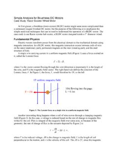
5 Field winding - The winding through which a current is passed to produce flux (for the electromagnet). Windings are usually made of copper. DC MOTORS 3. dc motor Basic Principles Energy Conversion If electrical energy is supplied to a conductor lying perpendicular to a magnetic field, the interaction of current flowing in the conductor and the magnetic field will produce mechanical force (and therefore, mechanical energy). Value of Mechanical Force There are two conditions which are necessary to produce a force on the conductor. The conductor must be carrying current, and must be within a magnetic field. When these two conditions exist, a force will be applied to the conductor, which will attempt to move the conductor in a direction perpendicular to the magnetic field. This is the basic theory by which all DC MOTORS operate. The force exerted upon the conductor can be expressed as follows. F = B i l Newton (1). where B is the density of the magnetic field, l is the length of conductor, and i the value of current flowing in the conductor.
6 The direction of motion can be found using Fleming's Left Hand Rule. Figure 3: Fleming's Left Hand Rule The first finger points in the direction of the magnetic field (first - field), which goes from the North pole to the South pole. The second finger points in the direction of the current in the wire (second - current). The thumb then points in the direction the wire is thrust or pushed while in the magnetic field (thumb - torque or thrust). How much force will be created on a wire that is parallel to the magnetic field? 4 DC MOTORS Principle of operation Consider a coil in a magnetic field of flux density B (figure 4). When the two ends of the coil are connected across a DC voltage source, current I flows through it. A force is exerted on the coil as a result of the interaction of magnetic field and electric current. The force on the two sides of the coil is such that the coil starts to move in the direction of force. Figure 4: Torque production in a dc motor In an actual dc motor , several such coils are wound on the rotor, all of which experience force, resulting in rotation.
7 The greater the current in the wire, or the greater the magnetic field, the faster the wire moves because of the greater force created. At the same time this torque is being produced, the conductors are moving in a magnetic field. At different positions, the flux linked with it changes, which causes an emf to be induced (e = d /dt) as shown in figure 5. This voltage is in opposition to the voltage that causes current flow through the conductor and is referred to as a counter-voltage or back emf. Induced emf Flux Figure 5: Induced voltage in the armature winding of dc motor The value of current flowing through the armature is dependent upon the difference between the applied voltage and this counter-voltage. The current due to this counter-voltage tends to oppose the very cause for its production according to Lenz's law. It results in the rotor slowing down. Eventually, the rotor slows just DC MOTORS 5. enough so that the force created by the magnetic field (F = Bil) equals the load force applied on the shaft.
8 Then the system moves at constant velocity. Torque Developed The equation for torque developed in a dc motor can be derived as follows. The force on one coil of wire F =i l x B Newton Note that l and B are vector quantities Since B = /A where A is the area of the coil, Therefore the torque for a multi turn coil with an armature current of Ia: T = K Ia (2). Where is the flux/pole in weber, K is a constant depending on coil geometry, and Ia is the current flowing in the armature winding. Note: Torque T is a function of force and the distance, equation (2) lumps all the constant parameters (eg. length, area and distance) in constant K. The mechanical power generated is the product of the machine torque and the mechanical speed of rotation, m Or, Pm = m T. = m K Ia (3). It is interesting to note that the same DC machine can be used either as a motor or as a generator, by reversing the terminal connections. Electrical Electrical Power T T Power input m T Mechanical Mechanical T m output output input (a) motor action (b) Generator action Figure 6: Reversability of a DC machine Induced Counter-voltage (Back emf): Due to the rotation of this coil in the magnetic field, the flux linked with it changes at different positions, which causes an emf to be induced (refer to figure 5).
9 The induced emf in a single coil, e = d c /dt Since the flux linking the coil, c = Sin t Induced voltage : e = Cos t (4). 6 DC MOTORS Note that equation (4) gives the emf induced in one coil. As there are several coils wound all around the rotor, each with a different emf depending on the amount of flux change through it, the total emf can be obtained by summing up the individual emfs. The total emf induced in the motor by several such coils wound on the rotor can be obtained by integrating equation (4), and expressed as: Eb = K m (5). where K is an armature constant, and is related to the geometry and magnetic properties of the motor , and m is the speed of rotation. The electrical power generated by the machine is given by: Pdev = Eb Ia = K m Ia (6). dc motor Equivalent circuit The schematic diagram for a dc motor is shown below. A dc motor has two distinct circuits: Field circuit and armature circuit. The input is electrical power and the output is mechanical power.
10 In this equivalent circuit, the field winding is supplied from a separate DC voltage source of voltage Vf. Rf and Lf represent the resistance and inductance of the field winding. The current If produced in the winding establishes the magnetic field necessary for motor operation. In the armature (rotor) circuit, VT is the voltage applied across the motor terminals, Ia is the current flowing in the armature circuit, Ra is the resistance of the armature winding, and Eb is the total voltage induced in the armature. Ia If + Ra + Lf +. Vf VT. m, T. Eb Rf _ _. _. Field circuit Armature (rotor) circuit Figure 7: dc motor representation Voltage Equation Applying KVL in the armature circuit of Figure 7: VT = Eb + IaRa (7). where VT is voltage applied to the armature terminals of the motor and Ra is the resistance of the armature winding. Note: The induced voltage is typically represented by symbol e (or E) and the terminal voltage by v (or V). At standstill, the motor speed is zero, therefore back emf is also zero.