Transcription of 4041 Series — Heavy Duty
1 April 09C1commercial Door Controls4041 Series Heavy DutyThe LCN 4041 Series is a non-handed surface mounted door closer. A wide choice of options, mounting accessories and ease of installation offer maximum LCN 4041 Series is a Heavy duty door closer designed to be used on aluminium, hollow metal or wood swinging commercial interior/exterior doors and is ideally suited for hospitals, educational, institutional and other high traffic , fully reversible, non- handed door cylinder constructed of high strength cast iron for extra to 10,000,000 cycles. Fully adjustable 1-6 spring strength to suit door size and site set to size 3. Standard closer offers 3 installation options. - Regular (Pull side)- Top Jamb (Pull side)- Parallel Arm (Push side)Independent adjustment valves for adjusting backcheck, closing and latching adjustment valves are concealed behind the cover to prevent in arms and shoe brackets adapt to uneven mounting adjust dial (fast accurate spring tension) to help installers accurately adjust the closer to match the conditions of the application.
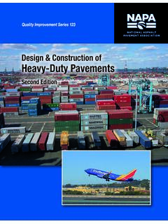
2 As spring power is adjusted, the size appears on the face of the template for fast, accurate installation. Cuts installation time in installed according to LCN installation instructions require minimal periodic maintenance or adjustments. Fire Rating: Refer to Appendix. Performance FeaturesLCN4041 RALS eriesFunctionFinishLCN 4041 Series ..LCN4041 Regular .. RHold Open .. HOAluminium .. ALSatin Stainless Steel .. SSSP olished Stainless Steel .. PSS1. Series Select the desired Series e .g . LCN 4041 Series .. LCN40412. Function Select the required function .. LCN4041R3. Finish Select the desired finish e .g . Aluminium .. LCN4041 RALS pecification GuidePictured: LCN 4041 - Standard CoverApril 09C2commercial Door Controls4041 SeriesCloser StrengthsSpecificationsDoor TypeTimber or MetalDoor SizeExternal Door 610mm - 1219mmInternal Door 610mm - 1524mmApplicationsRegular - Pull Side MountParallel Arm - Push Side MountTop Jamb - Push Side MountAdjustment ControlsClosing SpeedLatching SpeedBackcheckStrength1-6 AdjustableOptionsHold Open ArmAdaptor PlateParallel Arm Drop PlateSquare Metal CoverFinishAluminiumSatin Stainless SteelPolished Stainless SteelWarranty10 YearsPictured: LCN 4041 - Standard CoverPictured: LCN 4041 - Designer CoverThe LCN 4041 is designed for reduced opening force which when set to a 1 strength makes it suitable for use by people who are frail, aged or disabled.
3 This closer can operate at between 14-20Nm from initial opening up to 90 .Caution! Where door closers are installed and adjusted to meet reduced opening force requirements, there maybe insufficient power to reliably close and latch the door, depending on prevailing operating conditions. Note: In areas of high wind pressure and/or air conditioning pressures LCN Automatic Door Operators are Strength Selection ChartStrengthExterior DoorInterior Door 2NA610mm - 864mm 3610mm - 762mm864mm - 965mm 4762mm - 914mm965mm - 1219mm 5914mm - 1067mm1219mm - 1372mm 61067mm - 1219mm1372mm - 1524mmSelect strength based on width of doorApril 09C3commercial Door Controls4041 SeriesFunctionsRegular:For applications where the door must fully close after each opening. Hold-Open:Suitable for doors where the door may need to be left in a hold-open position. The hold-open function can be set to hold-open at a single point.
4 Hold-open closers can not be used on fire :Used predominantly on outward swinging doors in situations where it is not practical to fit a door stop. The Cush-N-Stop function has a built in stop incorporated into the arm to prevent damage to the closer, door or frame in the event of an abrupt stop. It is recommended that metal door frames be reinforced where the arm attaches to the transom. Maximum door opening 100 .Hold-Open Cush-N-Stop:Provides the same function as the Cush-N-Stop, but has the added feature of a hold-open function in the arm, which is engaged/disengaged by a tee handle. Maximum door opening 100 .Regulating ControlsThe LCN 4041 has independent regulators to control: Closing speed:Adjustment to increase or decrease the speed at which the door closes. This allows the appropriate momentum to close the door in a safe and secure manner. Closing speed adjustment operates from the maximum opening to 15.
5 Latching speed:The latching speed allows the door to close quietly and firmly. It can be adjusted to increase or decrease the speed at which the door finally closes. This assists the final stage of the closing cycle to help overcome stubborn latch bolts or air pressure conditions. Alternatively the latching speed can be decreased to cushion the door into the frame. The latching speed adjustment operates from 15 to closing. Backcheck:Adjustable hydraulic backcheck provides a cushioning effect when the door is forcibly thrown open to prevent damage to the closer, door and frame. The backcheck adjustment allows the level of resistance in the latter stage of opening to be set at the level required. Backcheck is effective from 75 . Backcheck is a requirement for all fire rated Adjustment:Spring strength may be increased or decreased by turning the allen head screw located in the end of the door closer 09C4commercial Door ControlsRegular (Pull Side) MountingRegular mounting has a maximum opening of 120.
6 The hold-open arm allows the door to be set at a hold-open point between 85 to 120 . The reveal should not exceed 19mm for a regular or hold-open arm. Top rail less than 95mm requires Adaptor Plate. Adaptor Plate requires a 51mm minimum top rail. Clearance of 70mm behind door is required for 90 installation. Top Jamb (Push Side) MountingTop jamb mounting has a maximum opening of 120 . The hold-open arm allows the door to be set at a hold-open point between 85 to 120 . A reveal of 65mm for regular and hold-open arms allows a 120 opening. Top rail requires 32mm minimum. Head frame requires 89mm minimum. Mounting Details - Standard Cover4041 Series311mm57mm279mm27mm19mm68mm265mm16m m89mm4040-1895mm57mm311mm17mm279mm89mm95 mm19mm30mm68mm264mmApril 09C5commercial Door Controls4041 SeriesInstallationLowers PA Shoe to clear 13mm blade Stop Spacer 4041-61 Provides anchorage for fifth screw used with Cush Arms where reveal is less than Shoe Support 4041-30 Parallel Arm (Push Side) MountingParallel arm mounting has a maximum opening of 180.
7 The hold-open arm allows the door to be set at one given hold-open point up to the maximum opening. Clearance for the PA Shoe is 102mm from door face. Top rail less than 140mm measured from the stop requires Drop Plate. The Drop Plate requires a 51mm minimum from the stop. Minimum stop width is 25mm. Blade stop clearance requires 13mm Blade Stop Spacer. When installing closers in parallel arm configuration, strength may be needed to be adjusted upwards to compensate for power (Pull Side) MountingCush arms can be templated for the following maximum opening/hold-open points:1. 85 - A = 202mm & B = 232mm2. 90 - A = 183mm & B = 216mm3. 100 - A = 154mm & B = 184mm4. 110 - A = 129mm & B = 162mmClearance for the Cush Shoe is 140mm from door face. Mounting Details - Standard Cover102mm57mm149mm125mm368mm102mm137mm3 11mm89mm137mm4040-18PA357mm102mm57mm152m mBA89mm311mm133mm133mm4040-18 PAApril 09C6commercial Door ControlsRegular (Pull Side) MountingRegular mounting has a maximum opening of 120.
8 The hold-open arm allows the door to be set at a hold-open point between 85 to 120 . The reveal should not exceed 19mm for a regular or hold-open arm. Top rail less than 95mm requires Adaptor Plate. Adaptor Plate requires a 51mm minimum top rail. Clearance of 70mm behind door is required for 90 installation. Top jamb mounting has a maximum opening of 120 . The hold-open arm allows the door to be set at a hold-open point between 85 to 120 . A reveal of 65mm for regular and hold-open arms allows a 120 opening. Top rail requires 32mm minimum. Head frame requires 89mm Jamb (Push Side) MountingMounting Details - Designer Cover4041 Series70mm279mm27mm19mm68mm265mm325mm9mm 101mm95mm4041-18DS170mm325mm279mm101mm95 mm30mm19mm68mm264mm10mmApril 09C7commercial Door Controls4041 SeriesInstallationBlade Stop Spacer 4041-61 Lowers PA Shoe to clear 13mm blade Shoe Support 4041-30 Provides anchorage for fifth screw used with Cush Arms where reveal is less than Arm (Push Side) MountingParallel arm mounting has a maximum opening of 180.
9 The hold-open arm allows the door to be set at one given hold open point up to the maximum opening. Clearance for the PA Shoe is 102mm from door face. Top rail less than 140mm measured from the stop requires Drop Plate. The Drop Plate requires a 51mm minimum from the stop. Minimum stop width is 25mm. Blade stop clearance requires 13mm Blade Stop Spacer. When installing closers in parallel arm configuration, strength may be needed to be adjusted upwards to compensate for power (Pull Side) MountingCush arms can be templated for the following maximum opening/hold-open points:1. 85 - A = 225mm & B = 220mm2. 90 - A = 206mm & B = 183mm3. 100 - A = 177mm & B = 154mm4. 110 - A = 152mm & B = 129mmClearance for the Cush Shoe is 140mm from door face. Mounting Details - Designer Cover102mm393mm102mm70mm85mm122mm325mm14 3mm137mm4041-18 PADS1149mm102mm357mm14 0mm139mm70mm95mmBA325mm139mm4041-18 PADS1 April 09C8commercial Door ControlsStandard, non-handed arm mounts hinge side or top jamb.
10 For parallel arm mounting, a PA Shoe is also required. Available in Aluminium Arm 4041-3077 Non-handed, hold-open arm mounts hinge side or top jamb. For parallel arm mounting, a PA Shoe is also required. Hold-open adjustable at shoe. Available in Aluminium Arm 4041-3049 Non-handed parallel arm features solid forged steel main arm and forearm, with stop in soffit shoe. Available in Aluminium Arm 4041-3077 CNSNon-handed arm, provides hold-open function with templated stop/hold open points. Hold-open controlled by tee handle. Available in Aluminium Cush-N-Stop Arm 4041-3049 CNSS tandard, non-handed cover, providing complete enclosure of closer body. Available in Aluminium Metal Cover 4041-DS1 Non-handed cover, providing complete enclosure of closer body. Available in Polished Brass, Polished Stainless Steel and Satin Stainless Steel Metal Cover 4041-MC4041 SeriesAccessoriesMounting plate required top jamb mounting where head frame is less than 60mm or a flush ceiling condition plate required top jamb mounting where head frame is less than 60mm or a flush ceiling condition Plate 4040-18 Adaptor Plate 4040-18DS1 Mounting plate required for parallel arm mounting configuration where top rail is less than 114mm, measured from the stop.