Transcription of 440/450 Electronic Vibration Switches
1 # 1004730 Rev J (October 2015) Page 1 of 10 OVERVIEWM etrix 440 and 450 electronic vibration switches provide eco-nomical, self-contained, single-channel Vibration protection. The 440 switch is suitable for use in non-hazardous as well as Class I Div 2 hazardous areas. The 450 switch utilizes the same internal electronics as the 440, but features explosion-proof enclosure styles suitable for Class I Div 1, Class II Div II, and Class III hazard-ous are available for Electronic (triac or FET) or electro-mechanical relay outputs, allowing the switch to be used in an auto-shutdown circuit that trips the machine under high vibra-tion conditions.
2 SR versions provide a single alarm setpoint and corresponding discrete output. DR versions provide two inde-pendent alarm setpoints and corresponding discrete outputs, allowing implementation of ALERT (pre-shutdown) and DANGER (shutdown) levels. A separate 4-20 mA proportional output is also provided on all switch models, allowing connection to PLCs, DCSs, strip chart recorders, or other process control systems where Vibration levels can be on both Switches is monitored in RMS velocity units. The standard configuration consists of an internal accelerometer mounted inside the switch housing, providing completely self-contained functionality.
3 The switch may also be configured to use an external accelerometer if desired.* * NOTE: Hazardous area approvals are not available when an external sensor is used with the model 440. Consider models 450 or SM6100 instead, which are approved for use in hazardous areas with a variety of external sensor types when Metrix sensor housing 7295 and explosion-proof wiring practices are Switches are an attractive solution when all of the fol-lowing criteria apply: Only one or two measurement points are required on a machine. A fully self-contained approach is desired or required (sens-ing element, signal conditioning, alarming, and outputs).
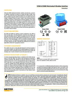
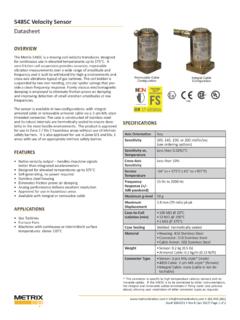
4 Sufficient room exists to mount a Vibration switch on the machine in the correct location and in the correct orienta-tion such that the Vibration levels indicative of machinery malfunctions will actually be measurable at the switch mounting location. The features of a multi-channel monitoring system are not necessary and cannot be financially justified. A 4-20mA Vibration transmitter is undesirable or impractical because a PLC, DCS, SCADA system, or other instrumenta-tion is not available for monitoring the transmitter situations where one or more of these criteria cannot be met, Metrix offers other solutions that may be more appropriate, such as Vibration transmitters and single-channel monitors that accept an external / 450 Electronic Vibration SwitchesDatasheet440 Switch The 440 switch is CSA approved for Class I Div 2 Groups B,C,D hazardous areas.
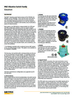
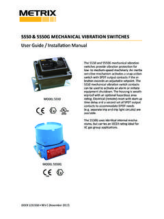
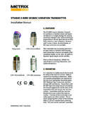
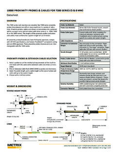
5 Its enclosure carries a NEMA 4X rating and uses a 3-hole mounting pattern. 450 Switch The 450 switch has the same internal electronics as the 440, but uses an explo-sion-proof enclosure for CSA-approved use in Class I Div1 Groups B,C,D, Class II Div 1 Groups E,F,G, and Class III areas. The standard enclosure (4-hole mounting pat-tern) is available with a solid cover with NEMA 4. The alternate enclosure (2-hole mounting pattern) is available with a win-dow cover with NEMA 3, 4, 4X, 7 & NEMA 4X ENCLOSURE450 (STANDARD EXPLOSION PROOF NEMA 4 ENCLOSURE, SOLID COVER)450 (ALTERNATE EXPLOSION PROOF NEMA 3, 4, 4X, 7 & 9 ENCLOSURE, WINDOW COVER)Seismic Measurements440/ 450 electronic vibration switches are intended for general-purpose seismic Vibration measurements on a wide range of rotating and reciprocating machinery with rotative speeds between 120 rpm and 6,000 rpm.
6 Seismic measurements are particularly well-suited for machines that incorporate rolling-element bearings because shaft Vibration in such machines is usually transmitted directly through the bearing to the bearing housing, without substantial damping or attenuation. Seismic transducers can also measure Vibration that does not originate at the shaft, such as bearing-related wear and defects, footing/foundation problems, piping resonances that are coupled to the machine, etc. Metrix does not recommend seismic measure-ments as the sole means of protecting machinery with fluid-film bearings where the shaft Vibration many not be faithfully transmitted to the measurement location.
7 Thought should be given to the efficacy of such a monitoring strategy before relying substantially or solely upon seismic # 1004730 Rev J (October 2015) Page 2 of 10 Why Measure Velocity?When a decision has been made to monitor seismic Vibration on the machine casing or support structure, velocity is often the best parameter to use. Acceleration and displacement levels are heavily influenced by the frequency(ies) at which the vibra-tion is occurring, while velocity levels are much less influenced. Thus, although acceleration, velocity, and displacement mea-surements are inter-related mathematically, seismic velocity measurements tend to be more consistent over a wide range of frequencies than either displacement or acceleration.
8 Conse-quently, broadband (sometimes called overall or unfiltered ) velocity measurements are appropriate for monitoring many machines as a reliable indicator of damaging vibratory energy, with the notable exception of machines that use fluid-film bearings, which are usually better addressed by shaft-observing proximity probes. Casing displacement is not a practical measurement to make directly, and is typically just an integrated seismic velocity measurement. As such, the primary decision when selecting a seismic measurement will usually be whether to measure casing velocity or casing acceleration.
9 As noted above, casing velocity will often be more appropriate because it tends to be a more reliable indicator of damaging vibratory energy over a broad frequency spectrum for low- to medium-speed : For machines with fluid-film bearings, shaft-observing proximity probes will provide more effec-tive Vibration measurements than seismic transducers due to the rotor dynamics of the machine and the attenua-tion of vibratory energy through a fluid-film boundary. Ac-cordingly, Metrix recommends and provides proximity probes and associated 4-20 mA transmitters or monitoring systems for such applications.
10 For machines with rolling element bearings and running speeds above 6,000 rpm, and/or where impulsive casing Vibration occurs, acceleration may be a better measurement than velocity. In such situations, it is recommended that you consult with your nearest Metrix sales professional who can review your application and assist with selection of the proper transducer type and associated transmitter or moni-toring system. FEATURES AND BENEFITS One or two independently adjustable setpointsThe use of two setpoints* (one for ALERT and one for SHUT-DOWN) is recommended for applications where it is desirable to remotely annunciate an ALERT condition to operators and/or maintenance personnel.