Transcription of 440S/PK232 INTERFACE BOX With the front panel …
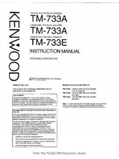
1 440S/PK232 INTERFACE BOX with the front panel switch in the up position the 440s speaker ( afsk Audio) is connected to the pk232 . Volume can be increased or decreased with the volume control on the 440s . with the front panel switch in the lower position the afsk Audio comes from the 3 afsk OUT Terminal and is a constant level. The INTERFACE box also connects afsk Audio from the pk232 to the440s afsk Audio in connector. 5A1l/3O67 5tJ 3 ;i PAN CO PaQc I fRACE -o C 4 tD5 Swi 2) JL-JQ AQ - -- I!. ' -- ------., \ IHIIrIIf IIIIII llllIIIIIII! N "Oman COME (, \ O .% .. , (* ____ I oHH 0 0 L' J Oscilloscope ud FSK Connector External Modem Connector 8-AAed AOO 'Model PK-23? 1y,WOOd WA 96036 sco ;s S 232 O AO*02 out '0' T3DC I I Radio 2 Connections CW Key Outputs - Radio 1 Connections Computer I/O Connector- -13 VDC Power Receptacle afsk Level Adjusting Pot Figure 2-2 PK-232 Rear panel Connections and controls )AirE,eFAc 51it'J - - CAJk'EC iji Coij#JEC,TO FROM qLfO cT Il RMc1i CoJA)& 0 To 496S I Tc9i ,3 FSI( 1*) AFS( OUT TTT At3Do SW 3 2 1 To Pi~l~,z Gob PXII Rcio 1.
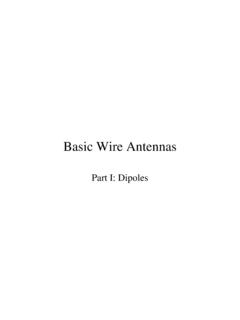
2 Ry, Autio (GEi) r)cPu DIiHITE) s' (&cK) GOwE) PTT (R ax OX C66 b CS I 232 OPERATING MANUAL INSTALLATION Please refer to section for more information on connections to specific computers, and APPENDIX K for connections to specific radios. The following two figures (Figures 2-1 and 2-2) show the front and rear panel controls, connectors and indicators. Please take a moment to familiarize yourself with them, as we will be referring to them throughout this manual. AOanced tioclOnC ApOt,CihOflt Model PK-232 ERROR CE PnRSC ST'8Y i0Dt L rEC 5Co -s 10 0 0 0 0 0110 0 0 0 0 r . DCO Io0000Jb0000 CO. nR CR n WORSEnKR )23 _ STATUS MODE 0? II Status and Mode LEDs I L Threshold Tuning Indicator Knob Radio 1/Radio 2 Switch - &- Indicator Power Switch Figure 2-1 PK-232 front panel Controls and Indicators Oscilloscope and FSK Connector dflrCed (lecivopuc Inc 98036 POWER LW MS-N ' P000 * P0010 2 ,3 OC y , , W External Modem Connector MOW[ P1(232 OUT\ -S-23210 cR06 IIi I?]
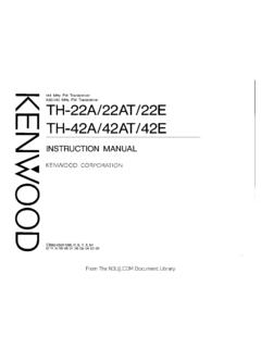
3 Cj)(j) I Radio 2 Connections CW Key Outputs Radio 1 Connections Computer I/O Connector 13 VDC Power Receptacle afsk Level Adjusting P0 Figure 2-2 PK-232 Rear panel Connections and controls System Quick-Check Verify that you've done these initial steps before going any further: o the ROM backup batteries are installed in the PK-232; o your PK-232 is connected to your computer via the RS-232-C cable; o ONLY PINS 1 THROUGH 8, and PIN 20 are connected; o your PK-232 is connected to a regulated DC supply; 2-3 pk232 -25 - - - PK-232 OPERATING MANUAL INSTALLATION Positive PTT Place the slip-on juniper across the center pin and the pin nearest the front of the unit. Replace the cover and six screws. Negative PTT Place the slip-on jumper across the center pin and the pin nearest the rear of the unit.
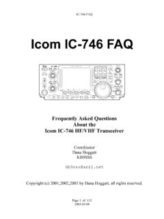
4 Replace the cover and six screws. FM Installation and Adjustment 1. Turn on your computer and PK-232 and start your terminal program. 2. Connect the radio to a dummy load; be prepared to monitor your transmissions with another nearby radio. 3. Verify that your PK-232 and FM radio are connected as shown in 1 Figure 2-3 below. I >10= 1 RX Will RID (110 IX 2 BLK RED PTT Gil RED PIT SHIELD 10 JorJ6 I Figure 2-3 Radio-to-PK-232 Connections 4. Enter the Calibrate mode by typing: 'CAL <RETURN>.' NOTE: In the Calibrate mode only, the 'K' key toggles the trans- mitter PTT line on and off. The 'SPACE BAR' toggles the PK-232's afsk tone generator from 'Mark' (the lower pitched tone) to 'Space' (the higher pitched tone).)
5 The PK-232 has a transmit watchdog timer circuit that unkeys your transmitter automatically after sixty (60) seconds. As you perform the following adjustments, unkey periodically, then rekey the transmitter by typing 'K.' 5. Press the 'K' key on the keyboard to key the transmitter. You should hear a continuous tone in the monitor receiver. 6. Tap the space bar several times until the higher pitched of the two tones ('space') is heard. 7. Press 'K' again to unkey the transmitter. 2-7 pk232 -29 - 3-9. OPERATION with A LINEAR AMPLI-FIER The figure below shows the frequencies relationship 2295Hz 2125Hz l7 OHzI I SSB Filter I Y I I icw Filter i I I 'I / \ SPACE MARK FIX CARRIER 3-8-2. Transmit Note: Key down periods of 1 hour will require a cool down period of approximately 30 minutes.
6 1. Ensure that your terminal is set up for afsk type keying. 2. Connect the terminal units afsk output jack to TS- 440s /44X afsk IN jack, and the terminal unit's afsk input jack to the TS- 440s /44X afsk OUT jack on the rear panel of the transceiver. The terminal units standby (PIT) terminal should be connected to the standby terminal on the REMOTE connector of the TS- 440s /44X. (See page 11 for the REMOTE terminal pin configuration.) 3. Place the MODE key on the TS- 440s /44X to afsk , and the Meter switch to ALC. 4. To transmit, either place the SEND/REC switch on the TS- 440s /44X to SEND, or use the PIT signal from your terminal unit. 5. When using afsk , you can also apply your trans-mit signal tones to pin number 1 of the microphone connector, if you do not wish to use the two jacks on the rear of the TS- 440s /44X.
7 To adjust the power output in afsk , increase or decrease the MIC gain control setting. A mid-scale ALC reading will yield full power output. Notes: 1. afsk operation requires terminal unit designed to supply this type of operation. You cannot use FSK tones with a afsk jack! 2. The afsk oscillator circuit should provide audio tones of 2125 and 2295 Hz. Lower tones may cause spurious output due to the higher harmonic content present with these lower frequencies. 3. The TS- 440s /44X and RTTY terminal unit should use separate power supplies, in order to prevent RFI (Radio Frequency Interference). 4. During afsk mode operation the microphone switch should be OFF, or the microphone discon-nected, if you are using the afsk jacks on the rear panel .
8 5. afsk operations utilize the LSB Mode. AMTOR uti-lizes USB, or reversed tone pairs. 6. The 4 FSK input level should be less than 100 mV. The TS- 440s /44X may be operated with any conven-tional linear amplifier which will accept up to approxi-mately 125 watts of RF drive, has a low current DC operated keying circuit, and returns approximately - 8 to - 1 VDC ALC back to the exciter. Please note that in order to operate full QSK (FULL break-in) the linear amplifier must also be QSK capable. Refer to the REMOTE connector diagram on page 11 and section Initial linear amplifier tune-up should be performed with the TS- 440s /44X set for approximately 50 watts Out-put to reduce wear and tear on both the linear, and the TS- 440s /44X.
9 Use of a dummy load is strongly recom-mended, since the bands are already sufficiently crowded. MODE switch S-meter This switch is used to select the mode of operation, FM1, This meter indicates receive input signal strength (S) or FM2, USB, CW, or LSB. The frequency step and the transmit output (RF). The upper scale is used for reading number of digits displayed are controlled by the DS switch. "S" in 558 or CW mode. The lower 1 0-division uniform scale is used in FM mode. (B31-0625-05) POWER/VOL control Push button type, power ON-OFF switch and volume con-trol are combined. Clockwise rotation will increase the volume. In the power OFF position , about current is drawn to back-up the micro-computer, and 6mA of leakage cur-rent to final module provided the power cable is connected to a constant power source.
10 To completely disable the transceiver, disconnect the power cable. SQUELCH control The squelch control is used to eliminate noise during no-signal time. Normally, this control is adjusted clockwise un-til the noise disappears and the BUSY lamp goes off (threshold level). HI/LOW switch This switch is used to set transmit output power to either 25W (high) or 5W (low) in FM or CW mode. In SSB mode, the power is high regardless of switch position . REV switch In receive, this switch is used to reverse the repeater shift ( 600 kHz) and other transmit/receive frequencies. It is a momentary non-lock type switch and returns to the normal out position when released. DS switch By using this switch, frequencies are shifted rapidly.