Transcription of 4425 Specification Document - JBL Professional
1 4425Bi-Radial Studio MonitorProfessional SeriesKey Features:Sensitivity: 91 dB SPL, 1 W at 1mFlat power response Bi-Radial horn High-frequency transducer: puretitanium diaphragm compressiondriver with edge-wound aluminumribbon voice coil, copper-platedpole piece, and diamond patterndiaphragm suspension Low-frequency transducer: 300 mm(12 in) driver with 76 mm (3 in)edge-wound copper ribbon voice coil200 watts continuous programpower capacitySmooth, accurate response from40 Hz to 16 kHzThe model 4425 Bi-Radial studiomonitor is designed for use in smallerstudios and for a variety of demandingaudio production in the case of the larger Bi-Radialmonitors, the 4425 maintains a 100-degree-by-loo-degree coverage pat-tern from its crossover frequency(1200 Hz) up to 16 kHz.
2 Smoothpower response is ensured from thelowest frequencies up to 1200 Hz, andflat power response is maintainedabove that frequency At the sametime, axial response is remarkablysmooth, and the combination of con-trolled power and axial responseensures that the reflected sound fieldin the control room will be free stereophonic imaging isachieved by creating an absolute sym-metrical sound field, the result ofmirror-image design. There is no lob-ing for normal off-axis listening posi-tions in the horizontal plane, andvertical lobing is minimized over thepreferred listening model 4425 can handle pro-gram power inputs of 200 watts, morethan enough to accommodate thehigh acoustical levels demanded incritical listening to today s Horn and DriverThe Bi-Radial horn is made of high-impact structural foam and is acousticallyinert.
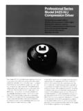
3 The high-frequency compression driver design makes use of a computer-machined phasing plug. Tolerances are held to a high degree, and unit-to-unitvariation is small. The diaphragm assembly is JBL s unique titanium design, withits advantages of extended frequency response relative freedom from mechni-cal fatigue, and high acoustical output capability. A copper shorting ring platedon the pole piece controls high-frequency impedance and improves high-frequency aligned phase response is maintained by the 4425 system over aforty-degree wide arc in the horizontal plane. The preferred listening arc in thevertical plane is between zero (on-axis) and ten degrees up.
4 See Figures 3 and4 for details of off-axis response of the TransducerThe model 2214H, 300 mm (12 in) driver, incorporates JBL s symmetrical fieldgeometry (SFG) magnet structure for low distortion. The 76 mm (3 in) voicecoil is made of edge-wound copper ribbon wire for highest sensitivity andpower handling. The inner suspension of this transducer has been designed toexhibit a progressive increase in restoring force with increasing controls dynamic offset for low-frequency, large excursion signals, andresults in reduced distortion at low frequencies. A composite coating on thecone optimizes both damping and stiffness, resulting in smoother response andlower Dividing NetworkIn addition to the normal function of frequency division, the network in the4425 provides power response compensation for the high-frequency controls allow the user to contour both mid and high frequencies to matchvarious room characteristics.
5 While the network slopes are 12 dB/octave, thecombination of inherent roll-off characteristics in both high- and low-frequencycomponents of the system with the electrical characteristics yields quite rapidtransitions in the crossover components are the most rugged, low-loss type, and high-qualitybypass capacitors are placed in parallel with the larger capacitors in the signalpath for increasing Patent #4,308,932 Foreign parents Patent #4,324,312. Foreign patents Bi-Radial Studio MonitorSpecifications:SMALL SIGNAL RESPONSEAND DIRECTIVITY:Frequency Response: 40 Hz - 16 kHz, 3 dBSensitivity (1 W @ 1m): 91 dB SPLE fficiency (Half-space reference) Angle (Included by6 dB down points, averagedbetween and 16 kHz).
6 Horizontal:100 ( + 10 , 30 )Vertical: 100 ( + 0 , 30 )Directivity(Averaged over 800 Hz to 16 kHz)Directivity Index (DI): 9 dB ( + 3, 2)Directivity Factor (Q): 8 (+ 8, 3)Group Delay Characteristics See figure 5300 Hz to kHz:400 S ( 100 s)smoothly changing kHz to 20 kHz:0 s (0, 50 S)ControlsMid Frequency: 11 to + 2 dB @ 2 kHzHigh Frequency: 8 to 0 dB @ 12 kHzNominal Impedance: 8 ohmsMinimum Impedance: > 6 ohms (see Figure 8)LARGE SIGNAL, INPUT ANDOUTPUT CHARACTERISTICS:Maximum Power Input :200 WShort-Term Peak3 (<10 ms): 1 kwContinuous Sine Wave : See Figure 9 Maximum SoundPressure Level (SPL)4 Continuous Program:114 dBContinuous Sine Wave: See Figure 10 Power Linearity1 W to 100 W Continuous input: <2 dB compression of(see Figure 11): SPL outputDistortion:At 100 dB SPL on-axis 1 meter: (10 W input)Second Harmonic:Low Frequencies (40-100 Hz): < 4%Mid Frequencies (100-1000 Hz): < l%High Frequencies(1000-8000 Hz): < 2%Third Harmonic:Low Frequencies: < 1%Mid Frequencies: < Frequencies: < 107 dB SPL on-axis 1 meter: (50 W input)Second Harmonic:Low Frequencies: < 3%Mid Frequencies:< Frequencies: < 6%Third Harmonic:Low Frequencies: < Frequencies: < Freaquencies: < information on Bi-Radial monitor loudspeakerdesign can be found in a paper by D.
7 Smith, D. Keele, Jr.,and J. Eargle, Improvements in Monitor LoudspeakerSystems: published in the Journal of the Audio Engineer-ing Society, Vol. 31, No. 6, June 1983. Copies are availablefrom JBL continually engages in research related to product improvement. New materials, pro-duction methods. and design refinements are introduced into existing products withoutnotice as a routine expression of that philosophy. For this reason, any current JBL productmay differ in some respect from its published description, but will always equal or exceedthe original design specifications unless otherwise stated. The graph of maximum input power (Fig. 9) indicates, at each frequency, the maximumcontinuous electrical input before 1) the systems thermal ratings are exceeded, or 2)mechanical ratings such as maximum woofer excursion are exceeded, whichever occursfirst The system can handle short term (less than 10 ms) peaks of some 8-10 dB above theindicated values as long as the long term average remains below the curve.
8 If appreciablesubsonic energy below 15 Hz is expected in the program material, second-order orhigher high-pass filtering should be used ahead of the power amplifier4 SPL in dB ref 20 Pa. These SPLs are measured in the reverberant field of a referenceroom of 85 m (3000 ft ) with an absorption of metric Sabins (200 ft ). The contin-uous program maximum SPL is based on the noise spectrum and power listed in thespecification for maximum continuous program power input (see note 2). The graph ofmaximum continuous sine wave SPL (Fig. 10) shows the maximum SPL the system cangenerate at each frequency when the input levels of Fig.
9 11 are (a) P. Garde, All-Pass Crossover System,"JAudio Eng. Soc, vol. 28 pp. 575-584(Sept 1980).(b) J. Blauert, P. Laws Group Delay Distortions in Electroacoustical Systems: J. Acoust. Soc, Am, vol. 63 pp 1478-1483 (May 1978).(c)H. Suzuki S Monta, T Shinco, On the Perception of Phase Distortion,"J. Audio Eng. Soc, vol. 28, pp 570-574 (Sept. 1980).(d) R. Lee Is Linear Phase Worthwhile," presented at the 68th Convention ofthe Audio Eng. Soc., Preprint 1732 (F-41, (Mar. 1981). Rating based on test signal of IEC filtered random noise with a peak-to-peak average ratioof 6 dB, two hours even-order allpass crossover network used in the system (a).)
10 The smooth delayresponse exhibited by the system is well below audibility thresholds as shown in (b-d). The high and low frequency transducers of the system are aligned vertically and thus areon the same acoustic source plane The indicated group delay characteristics for the sys-rem (Fie. 51 is entirely due to the gradually changing phase characteristic of the sharp-Net weight: 26 kg (57 lb)Shipping weight: kg (65 lb)Grille Color: Dark BlueEnclosure Volume (net): l( cu. ft.)Resonance Frequency: 34 HzFinish: Oiled WalnutDriver ComplementLow Frequency:2214 HCompression Driver:2416 HHorn:2342 Dimensions:635 mm high x 406 mm wide x311 mm deep(375 mm deep w/horn)25 in high x 16 in wide x 12 indeep(14 in deep w/horn)GENERAL:Crossover kHzFigure 1.)
