Transcription of 5–1. Determine the force in each member of the truss, D E C
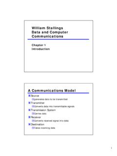
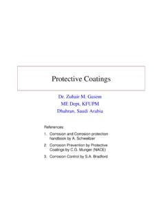
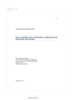
1 2011 Pearson Education, Inc., Upper Saddle River, NJ. All rights reserved. This material is protected under all copyright laws as they currently exist. No portion of this material may be reproduced, in any form or by any means, without permission in writing from the 5 the force in each member of the truss, and state if the members are in tension or compression. 2010 Pearson Education, Inc., Upper Saddle River, NJ. All rights reserved. This material is protected under all copyright laws as they currentlyexist. No portion of this material may be reproduced, in any form or by any means, without permission in writing from the N900 N2 m2 m2 mACEDB06a Ch06a 4016/12/09 8:48:31 AMMethod of Joints: We will begin by analyzing the equilibrium of joint D, and then proceed toanalyze joints C and D: From geometry, u = tan 1 = . Thus, from the free-body diagram in Fig. a, Joint C: From the free - body diagram in Fig. a, Joint E: From the free - body diagram in Fig. c, 12 FDC = N = kN (C) Ans FDE = 1200 N = kN (T) Ans FFB = N = kN (C) Ans+ c Fy = 0; cos FDE = 0 FEA = 2100 N = kN (T) Ans+ c Fy = 0; 1200 + cos FEA = 0+S Fx = 0; 600 FDC sin = 0 +S Fx = 0; 900 FEB sin 45 = 0 Fx = 0; FCE cos = 0 FCE = 0 Ans + Fy = 0; FCB = 0 FCB = N = kN (C) Ans + Note: The equilibrium analysis of joint A can be used to Determine the components ofsupport reaction at 2814/8/11 11:49:44 AM 2011 Pearson Education, Inc.
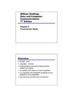
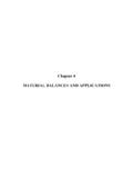
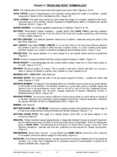
2 , Upper Saddle River, NJ. All rights reserved. This material is protected under all copyright laws as they currently exist. No portion of this material may be reproduced, in any form or by any means, without permission in writing from the truss, used to support a balcony, is subjected tothe loading shown. Approximate each joint as a pin anddetermine the force in each member . State whether themembers are in tension or compression. Set P2=400 lb, 2010 Pearson Education, Inc., Upper Saddle River, NJ. All rights reserved. This material is protected under all copyright laws as they currentlyexist. No portion of this material may be reproduced, in any form or by any means, without permission in writing from the ft4 ft45 DECBP2A4 ftP11 m1 m1 m3 kN2 kN3 kN3 kNmembers are in tension or compression. Set P1 = 3 kN, P2 = 2 A:+ Fy = 0; FAD sin 45 3 = 0 FAD = = kN (C) Ans+ Fx = 0; FAB cos 45 = 0 FAB = 3 kN (T) AnsJoint B:+ Fy = 0; FBD 2 = 0 FBD = 2 kN (C) Ans+ Fx = 0; FBC 3 = 0 FBC = 3 kN (T) AnsJoint D:+ Fy = 0; FDC sin 45 2 sin 45 = 0 FDC = kN = kN (T) Ans+ Fx = 0; cos 45 + cos 45 FDE = 0 FDE = kN (C) Ans06a Ch06a 4026/12/09 8:48:33 AM5 2824/8/11 11:49:44 AM 2011 Pearson Education, Inc.
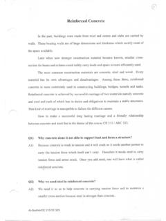
3 , Upper Saddle River, NJ. All rights reserved. This material is protected under all copyright laws as they currently exist. No portion of this material may be reproduced, in any form or by any means, without permission in writing from the truss, used to support a balcony, is subjected tothe loading shown. Approximate each joint as a pin anddetermine the force in each member . State whether themembers are in tension or compression. Set P2= lb, 2010 Pearson Education, Inc., Upper Saddle River, NJ. All rights reserved. This material is protected under all copyright laws as they currentlyexist. No portion of this material may be reproduced, in any form or by any means, without permission in writing from the ft4 ft45 DECBP2A4 ftP11 m1 m1 m4 kN4 kNmembers are in tension or compression. Set P1 = 4 kN, P2 = A:+ Fy = 0; FAD sin 45 4 = 0 FAD = kN = kN (C) Ans+ Fx = 0; FAB cos 45 = 0 FAB = kN (T) AnsJoint B:+ Fy = 0; FBD 0 = 0 FBD = 0 Ans+ Fx = 0; FBC 4 = 0 FBC = 4 kN (T) AnsJoint D:+ Fy = 0; FDC sin 45 0 sin 45 = 0 FDC = kN = kN (T) Ans+ Fx = 0; cos 45 + cos 45 FDE = 0 FDE = kN (C) Ans06a Ch06a 4036/12/09 8:48:36 AM5 2834/8/11 11:49:44 AM 2011 Pearson Education, Inc.
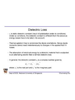
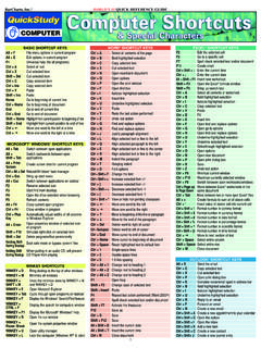
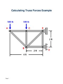
4 , Upper Saddle River, NJ. All rights reserved. This material is protected under all copyright laws as they currently exist. No portion of this material may be reproduced, in any form or by any means, without permission in writing from the *6 the force in each member of the trussand state if the members are in tension or each joint as a pin. Set P= 4 kN. 2010 Pearson Education, Inc., Upper Saddle River, NJ. All rights reserved. This material is protected under all copyright laws as they currentlyexist. No portion of this material may be reproduced, in any form or by any means, without permission in writing from the m4 m4 m06a Ch06a 4046/12/09 8:48:38 AMJoint AJoint BJoint EJoint D FAE = kN (C) = kN (C) Ans+ c Fy = 0; FAE 4 = 0 Fx = 0; + sin + sin FED = 0 + Fy = 0; FEC cos cos = 0 FEC = kN (T) = kN (T) Ans FED = kN (C) = kN (C) Ans + Note: The support reactions, Cx and Cy can be determined by analysing Joint C using the results obtained above.
5 Method of Joints: In this case, the support reactions arenot required for determining the member FAB = kN (T) Ans S Fx = 0; FAB = 0 +S Fx = 0; FBC = 0 FBC = kN (T) Ans+ c Fy = 0; FBE 8 = 0 FBE = kN (C) Ans+25 + c Fy = 0; FDC = 0 FDC = kN (T) Ans15 S Fx = 0; Dx = 0 Dx = kN25 +*5 2844/8/11 11:49:45 AM 2011 Pearson Education, Inc., Upper Saddle River, NJ. All rights reserved. This material is protected under all copyright laws as they currently exist. No portion of this material may be reproduced, in any form or by any means, without permission in writing from the 6 that each member of the truss is made of steelhaving a mass per length of 4 kg/m. Set , Determine theforce in each member , and indicate if the members are intension or compression. Neglect the weight of the gusset platesand assume each joint is a pin. Solve the problem by assumingthe weight of each member can be represented as a verticalforce, half of which is applied at the end of each 2010 Pearson Education, Inc.
6 , Upper Saddle River, NJ. All rights reserved. This material is protected under all copyright laws as they currentlyexist. No portion of this material may be reproduced, in any form or by any means, without permission in writing from the m4 m4 m06a Ch06a 4056/12/09 8:48:39 AMMethod of Joints: In this case, the support reactions arenot required for determining the member Forces:FA = 4( ) = NFB = 4( ) (2 + 2 + 1) = N202 +2 FD = 4( ) = N202 +2 FE = 4( ) = N201 + 32 FAE = (C) = 372 N (C) Ans+ c Fy = 0; FAE = 015 FAB = N (T) = 322 N (T) Ans S Fx = 0; FAB = 0 +25 Joint AJoint BS Fx = 0; FBC = 0 FBC = 332 N (T) Ans+ c Fy = 0; FBE = 0 FBE = N (C) = 196 N (C) Ans+Joint E Fx = 0; + ( + ) sin + Fy = 0; FEC cos ( + ) cos = 0 FEC = N (T) = 558 N (T) Ans FED = N (C) = 929 N (C) Ans FDC = 582 N (T) Ans + + sin FED = 0 Joint D+ c Fy = 0; + FDC = 015 5 2854/8/11 11:49:45 AM 2011 Pearson Education, Inc.
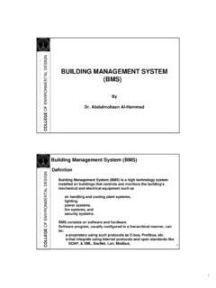
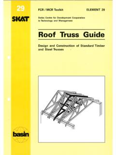
7 , Upper Saddle River, NJ. All rights reserved. This material is protected under all copyright laws as they currently exist. No portion of this material may be reproduced, in any form or by any means, without permission in writing from the the force in each member of the truss andstate if the members are in tension or compression. Setand .P2= kNP1=2 kN 2010 Pearson Education, Inc., Upper Saddle River, NJ. All rights reserved. This material is protected under all copyright laws as they currentlyexist. No portion of this material may be reproduced, in any form or by any means, without permission in writing from the m3 mP2P106a Ch06a 4066/12/09 8:48:40 AMMethod of Joints: In this case, the support reactions arenot required for determining the member DJoint CS Fx = 0; FDE = 0 FDE = kN (C) Ans+ c Fy = 0; FDB 2 = 0 FDB = kN (T) Ans+ c Fy = 0; FCB sin 30 = 0 FCB = kN (T) Ans+S Fx = 0; FCD cos 30 = 0 Ans FCD = kN (C) = kN (C) Ans+Joint B Fx = 0; ( + ) sin 30 + FBA = 0 + Fy = 0; FBE cos 30 cos 30 = 0 FBE = kN (C) Ans FBA = kN (T) Ans + Note: The support reactions at support A and E can be determined by analysing Joints A and E respectively using the results obtained above.
8 5 2864/8/11 11:49:45 AM 2011 Pearson Education, Inc., Upper Saddle River, NJ. All rights reserved. This material is protected under all copyright laws as they currently exist. No portion of this material may be reproduced, in any form or by any means, without permission in writing from the the force in each member of the truss andstate if the members are in tension or compression. kN 2010 Pearson Education, Inc., Upper Saddle River, NJ. All rights reserved. This material is protected under all copyright laws as they currentlyexist. No portion of this material may be reproduced, in any form or by any means, without permission in writing from the m3 mP2P106a Ch06a 4076/12/09 8:48:42 AMMethod of Joints: In this case, the support reactions are not required for determining the member CJoint DJoint BNote: The support reactions at support A and E can be determined by analyzing Joints A and E respectively using the results obtained above.+c Fy = 0; FCB sin 30 4 = 0 FCB = kN (T) AnsS+ Fx = 0; FCD cos 30 = 0 FCD = kN (C) = kN AnsS+ Fx = 0; FDE = 0 FDE = kN (C) Ans+c Fy = 0; FDB 4 = 0 FDB = kN (T) AnsQ+ Fy = 0; FBE cos 30 cos 30 = 0 FBE = kN (C) AnsR+ Fx = 0; ( + ) sin 30 + FBA = 0 FBA = kN (T) Ans5 2874/8/11 11:49:46 AM 2011 Pearson Education, Inc.
9 , Upper Saddle River, NJ. All rights reserved. This material is protected under all copyright laws as they currently exist. No portion of this material may be reproduced, in any form or by any means, without permission in writing from the *6 the force in each member of the truss, and state if the members are in tension or compression. 800 lb 2010 Pearson Education, Inc., Upper Saddle River, NJ. All rights reserved. This material is protected under all copyright laws as they currentlyexist. No portion of this material may be reproduced, in any form or by any means, without permission in writing from the ft3 ft3 ftP3 ft500 lbACBDFE1 m1 m1 m1 kNFFE = kNFAF = kNFBC = kNFAB = 4 kNFFB = kN4 kNP = 4 of Joints: We will analyze the equilibrium of the joints in the following sequence:A F E B A: From the free body diagram in Fig. a,+ Fy = 0; FAF sin 45 4 = 0 FAF = kN (T) Ans+ Fx = 0; cos 45 FAB = 0 FAB = 4 kN (C) AnsJoint F: From the free body diagram in Fig.
10 B,+ Fy = 0; FFB cos 45 cos 45 = 0 FFB = kN (C) Ans+ Fx = 0; FFE sin 45 sin 45 = 0 FFE = kN (T) AnsJoint E: From the free body diagram in Fig. c,+ Fx = 0; FED = 0 FED = kN (T) Ans+ Fy = 0; FEB = 0 AnsJoint B: From the free body diagram in Fig. d,+ Fy = 0; FBD sin 45 sin 45 = 0 FBD = kN (T) Ans+ Fx = 0; 4 + cos 45 + cos 45 FBC = 0 FBC = kN (C) AnsJoint C: From the free body diagram in Fig. e,+ Fy = 0; FCD = 0 Ans+ Fx = 0; NC = 0 NC = kN Ans06a Ch06a 4086/12/09 8:48:42 AM*5 2884/8/11 11:49:46 AM 2011 Pearson Education, Inc., Upper Saddle River, NJ. All rights reserved. This material is protected under all copyright laws as they currently exist. No portion of this material may be reproduced, in any form or by any means, without permission in writing from the 2010 Pearson Education, Inc., Upper Saddle River, NJ. All rights reserved. This material is protected under all copyright laws as they currentlyexist.