Transcription of 5-5 DESIGN CRITERIA OF STANDARD EARTH RETAINING …
1 MeMo to Designers 5-5 April 2014. LRFD. 5-5 DESIGN CRITERIA of STANDARD EARTH RETAINING systems Introduction With the implementation of AASHTO Load and Resistance Factor DESIGN (LRFD) Bridge DESIGN Specifications (AASHTO DESIGN Specifications) a new set of EARTH RETAINING Systems (ERS) have been produced and published as STANDARD Plans or Revised STANDARD Plans. Similarly, a new set of Bridge STANDARD Details (XS sheets) related to ERS have been produced and added to the working set of Bridge STANDARD Details. This memo summarizes the DESIGN CRITERIA and assumptions used to produce the new plans. This memo is not intended to include every aspect of DESIGN in the AASHTO DESIGN Specifications, nor is this memo intended as a substitute for the AASHTO DESIGN Specifications. The DESIGN parameters for DESIGN of these ERS are based on the AASHTO DESIGN Specifications, 4 th edition, 2007, and the 2010 California Amendments (California Amendments).
2 ERS that appear as 2010 STANDARD Plans or Revised STANDARD Plans are: RETAINING Walls Type 1, 1A, 5 and 6. Crib Walls made of reinforced concrete or steel ERS that appear as Bridge STANDARD Details are RETAINING Walls Type 7. Modified RETAINING Walls supporting sound walls, Type 1SW series and Type 5SW. series and Type 7SW series Mechanically Stabilized Embankment (MSE). DESIGN Parameters and Assumptions a) Material Properties The soil parameters and material properties assumed for DESIGN purposes are consistent with the 2010 STANDARD Specifications and STANDARD Special Provisions. Accordingly, these values are the default values utilized in the DESIGN of the STANDARD Plans and the Bridge STANDARD Details. Project specific parameters must be used when materials available for use on that project result in greater force effects on ERS, and the STANDARD designs should be re-evaluated for the project in such cases.
3 5-5 DESIGN CRITERIA of STANDARD EARTH RETAINING systems 1. MeMo to Designers 5-5 April 2014. LRFD. Soil Backfill Parameters Unit Weight of Soil, s = 120 pcf Soil Cohesion, c = 0. Internal friction angle, =34 for the backfill and foundation soil of all ERS except MSE. Internal friction angle, =34 for the reinforced soil of MSE. Internal friction angle, =30 for the retained soil (behind the reinforced soil) and foundation soil (below the reinforced soil) of MSE. Material Properties of Reinforced Concrete Elements Compressive Strength of Concrete at 28 days , fc' = ksi ( ksi for MSE panels). Reinforced Concrete Unit Weight, c = 150 pcf Minimum Yield Strength of Reinforcing Steel, fy = 60 ksi b) Drainage and Compaction Sufficient and appropriate drainage details are assumed to be provided in the reinforced soil and the retained soil. Hence no water pressure is considered in the DESIGN .
4 Also, no compaction loads are considered in the DESIGN , since the construction methods allowed in the STANDARD Specifications prevent inducing any additional stress in the structures. STANDARD DESIGN Considerations a) Limit States and Load Combinations Service Limit State I, Strength Limit State I and Extreme Event Limit State I (earthquake). shown in Table of the California Amendments were considered for DESIGN of all STANDARD ERS RETAINING backfill supporting highway traffic. Note that load combination Strength IV in Table not applicable to ERS. The load combinations used were, Service Limit State I. + + + 2 5-5 DESIGN CRITERIA of STANDARD EARTH RETAINING systems MeMo to Designers 5-5 April 2014. LRFD. Strength Limit State I. + + + for Ia (bearing, structure capacity). + + + for Ib (sliding, bearing, structure capacity). Extreme Event Limit State I. + + + + for all ERS except crib walls + + + for crib walls (For Extreme Event Limit State I, live load surcharge is not considered).
5 Where: DC = the self weight of structural components EV = the self weight of the soil above the heel of a footing in a semi-gravity RETAINING wall or of the reinforced soil in a MSE. EH = static soil lateral load LS = live load surcharge EQE = dynamic soil lateral load EQD = the inertia from EV and DC. Numerically, EQD is equal to the horizontal seismic coefficient, kh, times EV plus kh times DC except for the case of the crib walls, where EQD equals kh times EV. More information about Extreme Event Limit State I can be found in section d) Seismic DESIGN . At the Service Limit State, the ERS is evaluated for eccentricity, and structural service performance, such as member deformation ( the stem deflection on a Type 1 wall), cracking, temperature, and shrinkage requirements (in the case of the STANDARD ERS built with reinforced concrete). At the Strength Limit States, the ERS is evaluated so that sliding limits and structural strength are not exceeded.
6 At Extreme Event Limit State I, the ERS. is evaluated so that eccentricity, sliding limits, and structural strength are not exceeded. The bearing stresses of each ERS are provided for project specific use of all STANDARD ERS. designs. Similarly, overall stability and settlement must be considered for project specific use of these designs. Table 1 summarizes DESIGN considerations for all STANDARD ERS. 5-5 DESIGN CRITERIA of STANDARD EARTH RETAINING systems 3. MeMo to Designers 5-5 April 2014. LRFD. Table 1 Analysis for ERS DESIGN Limit State Service I Strength Ia Strength Ib Extreme Event I (Seismic). Bearing Stresses* X X X X. Eccentricity X X. Sliding X X. Structural Service X. Performance Structural Capacity X X X. * To be checked against actual project conditions before use of the STANDARD Load combinations for concrete RETAINING walls supporting sound walls or containing ground anchors have slightly different load combinations than other STANDARD ERS.
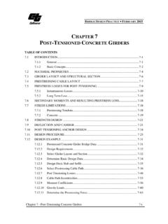
7 The load combinations for those ERS include force effects of the wind load on the sound wall, the inertial force of the sound wall for seismic events, and the prestress force from the vertical ground anchors. These walls form part of the Bridge STANDARD Details (XS sheets), and their respective loading can be found on those sheets. Load factors are chosen to create maximum force effect for a given load combination. Strength Limit State I is separated into Strength Ia and Strength Ib using load factor values as shown in Figure 1. These load combinations are also illustrated in Section of the AASHTO DESIGN Specifications. The loads depicted in Figure 1 are shown applied to a semi-gravity wall, but are applied to all STANDARD ERS. 4 5-5 DESIGN CRITERIA of STANDARD EARTH RETAINING systems MeMo to Designers 5-5 April 2014. LRFD. Figure 1 Limit States and Load Combinations 5-5 DESIGN CRITERIA of STANDARD EARTH RETAINING systems 5.
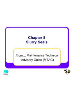
8 MeMo to Designers 5-5 April 2014. LRFD. b) STANDARD Loading Cases The loading case numbers ( Case 1, Case 2, and Case 3) assumed in the STANDARD designs should not to be confused with the limit state load combination numbers in the LRFD. methodology previously discussed. The STANDARD loading cases depict the backfill and live load surcharge configurations used in the DESIGN . There are two STANDARD loading cases, Load Case 1 and Load Case 2. Load Case 1 has a traffic live load on a horizontal backfill, and Load Case 2 has a backfill slope of two horizontal to one vertical (2:1) for a specified distance and then turns level afterwards. Minor variations in loading cases occur according to ERS types . Some STANDARD ERS have additional loading cases that are considered and are shown on the respective standards. When additional project specific loading is required on the ERS, the STANDARD designs can no longer apply to the project without special DESIGN .
9 The STANDARD loading cases are shown in Figure 2. Figure 2 STANDARD Loading Cases c) Live Load Surcharge The Live Load Surcharge is positioned to produce the maximum DESIGN load. In Figure 1, where a semi-gravity wall is shown, the Live Load Surcharge is placed over any element of the ERS for settlement and bearing analysis, while the Live Load Surcharge is placed behind all the elements of the ERS for sliding, and eccentricity analysis. Note that the Live Load Surcharge is not applied to the sloped portion of the backfill depicted by the dashed lines in Figure 1, or anywhere on the backfill for Extreme Event Limit State I. 6 5-5 DESIGN CRITERIA of STANDARD EARTH RETAINING systems MeMo to Designers 5-5 April 2014. LRFD. d) Seismic DESIGN The seismic DESIGN of the STANDARD ERS is performed using either Mononobe-Okabe (MO). Method for Loading Case 1 (a backfill with a planar surface and no live load surcharge), or the trial wedge method for Loading Case 2.
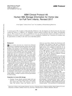
10 The Trial Wedge Method is similar to the MO. Method and is used for the other Loading Cases where the backfill surface is not planar. As a result of analysis using the MO Method, the resultant of seismic soil pressure, PAE, is obtained. All STANDARD ERS are designed using the CRITERIA in the 2010 California Amendments for seismic load. The 2010 California Amendments assumes that the total soil thrust, PAE, is separated into two components, the static active soil pressure in a triangular shape and the dynamic soil pressure in a rectangular shape, as shown in Figure 3. + =. H. PAE. 1. 2 H. 1. 3 H ha static dynamic total soil soil soil pressure pressure pressure Figure 3 Seismic Loading (Reference: 2010 California Amendments). Therefore, the total soil lateral load estimated using the MO method or a similar trial wedge method was a function of the horizontal seismic coefficient, kh, the vertical seismic coefficient, kv , and the soil internal friction angle.