Transcription of 10-20 GIRDER REINFORCEMENT
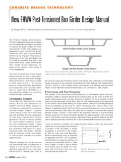
1 GIRDER design DETAILS 10-20 JUNE 201010-20 GIRDER REINFORCEMENTBox GIRDER ReinforcementThe designer will ordinarily furnish moment diagrams with the number, size, and lengthsof main ReinfBOTTOM ReinfC Abut 1LC BENT 2L1615 2123413524472637292319161310825231917141 21082950 EACH LINE EQUALS 2 - 11 BARSCont SYMMETRICAL ABOUT C SPAN 2L65 -0 123 -0 #The main REINFORCEMENT should be placed so that the ends are staggered rather than beingprogressively shorter. 241218815241815128 CorrectIncorrectBars should be symmetrical about the centerline of bay and the shorter bars shouldgenerally be placed nearer the centerline of convenience in these instructions, only an interior GIRDER will be of an exterior GIRDER is design DETAILS 10-20 JUNE 2010 GIRDER GIRDER ReinforcementIt is considered good practice to use as few bar lengths as possible in order to simplify shopdetailing, cutting, handing and placing.
2 Also, maximum bar lengths should be kept shorterthan 60' whenever possible. It is usually possible to use many bars of the same length byadding a foot or two to a couple of bars. This condition is usually obtained by combining thelongest cutoff on one side of the centerline with the shortest on the opposite side. A few oddlengths are often required. The lengths for top REINFORCEMENT for this example would be as follows:37292319161310881210141719232545 '41'33'33'33'32'33'33'use 33'Thus by adding one foot to one of the bars, six identical length bars are GIRDERLC GIRDERLC BENTLNOTE CNOTE BNOTE BNOTE ANOTE A4 NOTE D372388882929131910101010191323161637171 725251212202014142323# two continuous bars in web at top of bars under bend of deck REINFORCEMENT .
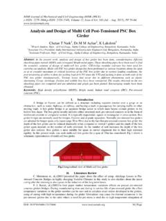
3 Continuous REINFORCEMENT should alsobe placed at the edge of deck slab and adjacent to barrier dowels. See BRIDGESTANDARD PLAN BO-5, DETAIL these bars at approximately equal bar spacing shall not exceed 18 inches. Use additional #4 bars lappedwith main REINFORCEMENT where design DETAILS 10-20 JUNE 2010 Bottom GIRDER ReinforcementThe bars in the bottom REINFORCEMENT usually are long enough that the contractor must splicethem to meet hauling and handling limitations. It is possible to combine lengths advantageouslyhere also.
4 The length for the middle span for this example would be as follows: 2435414750504741352474'82'82'82'74'60606 0606014'22'22'22'14'Usual length limitationnet length needed plussplice lengthThus by combining lengths some similarity can be obtained and splices can be staggeredaway from maximum GIRDERLC GIRDERLContC SPAN 2 LNOTE BNOTE A353541414141474724244747353524245050505 0 continuous or other bars in the position required for maximum spacing of nominalreinforcing. This eliminates having a nominal bar paralleling and close to a main longitudinal REINFORCEMENT , #6 @ splice locations.
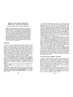
5 Do not show on plans. Note staggering design DETAILS 10-20 JUNE 2010 GIRDER GIRDER Reinforcement1. Top REINFORCEMENT shall be detailed similar to Box Bottom REINFORCEMENT shall be treated similar to Box GIRDER . REINFORCEMENT shall bedetailed by the GIRDER as shown SPANLC BENTLC AbutLContCHECK WITH THE DESIGNERFOR HOOK REQUIREMENTSAA2020102323131310 SECTION A-AContGIRDER design DETAILS 10-20 JUNE 2010 Layout of Bars in Stem of T-Beam1 #43 11 3 1 12 ClrClr1 #43 1 -1 3 1 12 ClrClr No. OF BARS* No.
6 OF BARS* *NOTE: ''X'' = distance from bottom of stem to center of gravity of #11 bars.