Transcription of New FHWA Post-Tensioned Box Girder Design Manual
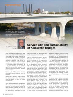
1 CONCRETE bridge TECHNOLOGY. New FHWA Post-Tensioned Box Girder Design Manual by Reggie Holt, Federal Highway Administration, and John Corven, Corven Engineering The Federal Highway Administration (FHWA) is pleased to announce the release of a new Manual for the analysis and Design of concrete box- Girder bridges. The post - tensioned Box Girder Design Manual was developed as a part of the FHWA project Advancing Steel and Concrete bridge Technology to Improve Infrastructure Performance. Brian Kozy and Reggie Holt of FHWA are providing direction to the project team led by Lehigh University and that includes Corven Engineering. The author of the Manual is John Corven of Corven Engineering. Figure 1. Typical concrete box- Girder cross section. All Figures: Developed by Corven The Post-Tensioned Box Girder Design Engineering for the Federal Highway Administration.
2 Manual focuses on cast-in-place, post - tensioned concrete box- Girder bridges with superstructure cross sections similar the concrete (creep and shrinkage) and the prestressing steel (relaxation) are presented. to those shown in Fig. 1. The Manual Design provisions of the American Association of State Highway and Transportation serves as a resource to state departments Officials' AASHTO LRFD bridge Design Specifications that address prestress losses of transportation and consulting firms related to time-dependent material characteristics are presented in a later chapter. that are exploring the benefits of, or are looking for guidance on, using this Prestressing with post -Tensioning method of bridge construction. Two chapters of the Manual deal with the mechanics of prestressing a Girder with post - tensioning.
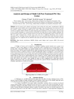
3 Chapter 3 presents typical stress summaries that are the result of Girder self- Introductory Chapters weight, superimposed loads, and post -tensioning. Equations for the summation of total The FHWA Post-Tensioned Box Girder stress are then rearranged in two useful ways, so that the prestressing force required at Design Manual was developed for a cross section can be found directly for a given tendon eccentricity and the permissible engineers who have limited exposure to limits of eccentricity can be found for a given prestressing force. Figure 2, taken from the Design and construction of prestressed Chapter 3, graphically depicts the first of these two, where the internal moment resulting concrete bridges. Chapter 1 presents from the prestressing, taken about the upper kern, is equated to the externally applied a brief history of the use of the bridge bending moment.
4 Chapter 3 also presents the geometric features of post -tensioning type and describes the basic components tendons comprised of a series of parabolic profiles, the tendon geometry most commonly of a box- Girder superstructure. Typical used in cast-in-place concrete box- Girder construction. These geometric features are then geometries of post -tensioning tendons used to evaluate secondary moments due to the prestressing of continuous-span girders . for cas t-in-place concrete bridges are also presented in Chapter 1, along Losses in prestress resulting from tendon friction, wobble, anchor set, and elastic with descriptions and photographs of shortening are developed and presented the components that comprise a post - in Chapter 4. The calculation of tendon tensioning tendon. This chapter concludes elongations is presented in this chapter, with an overview of the construction as well as lump-sum time-dependent of cast-in-place concrete box- Girder losses in prestressing force as predicted superstructures.
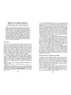
5 By applicable AASHTO LRFD guidelines. Considerations for single-end and two-end Material characteristics of the concrete stressing are discussed. Figure 3, taken and prestressing steel are presented in from Chapter 4, shows a typical tendon Chapter 2 of the Manual . Pertinent time- force diagram along the length of a three- dependent characteristics in accordance span, post -tensioning tendon after two- Figure 2. Equilibrium of internal and with the CEB-FIP Model Code (1990) of end stressing and anchor set. external moments. 40 | ASPIRE Summer 2016. verification of strength limit states in accordance with the AASHTO LRFD. specifications. Box- Girder superstructures require analysis and Design in the transverse direction. Chapter 8 presents both the approximate Design method from the AASHTO LRFD specifications and a generalized approach to transverse analysis and Design for single-cell box- Girder superstructures.
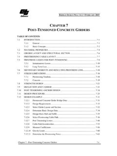
6 Chapter 9 presents three important Design considerations for Post-Tensioned box- Girder bridges, beginning with a detailed look into the local behavior of tendons in curved concrete members, depicted in Fig. 4. Both in-plane and out- of-plane force effects and resistances are presented. This information is followed by a discussion of end anchorage zones and the transfer of superstructure loads to the substructure through diaphragms for both nonintegral and integral superstructures. Figure 3. Tendon force diagram after stressing from both ends. Preliminary Design Useful Appendices The Post-Tensioned Box Girder Design Chapter 5 walks through the preliminary Design process for a cast-in-place, post - Manual includes four useful Appendices. tensioned box- Girder bridge using a three-span continuous bridge as an example.
7 Appendix A presents a hand method Guidelines for the dimensions of the box- Girder superstructure, both of the overall of structural analysis of indeterminate Girder and the members of the cross section, are presented. This is followed by the s t ru c t u r e s t h e M e t h o d o f Join t longitudinal analysis of the bridge to determine bending moments at critical sections. Flexibilities. This flexibility-based method, post -tensioning tendon profiles and the number of strands in the tendons are selected which relates simple-span Girder rotations based on the required prestressing force at each critical section. The jacking force of to continuity moments in continuous the tendons (Pjack) is established based on understanding the force in the tendon along structures, is an excellent tool for its length. Finally, service limit states are verified, substantiating the preliminary Design .
8 Analyzing Post-Tensioned structures where tendon paths are quickly integrated as Cast-in-place box- Girder bridges are often constructed monolithically with supporting curvature diagrams to produce simple columns. Chapter 6 presents additional Design considerations when the substructure span end rotations. Appendix B presents is integral with the superstructure. Superstructure bending moments caused by the fundamental torsional characteristics restraint of the integral substructures are evaluated. The load cases discussed include of single- and multi-cell box- Girder temperature rise and fall, temperature gradient, concrete creep, and concrete shrinkage. structures. Equations for shear flow and the torsional constant for cross Final Design sections are presented in this Appendix. Chapters 7, 8, and 9 of the Post-Tensioned Box Girder Design Manual focus Appendices C and D contain Design on final Design .
9 Longitudinal superstructure analysis and Design are addressed examples for three-span continuous in Chapter 7. Guidelines for computer modeling of Post-Tensioned box girders bridges. are presented in this chapter. Modeling concepts for s traight and cur ved bridges, with or without integral substructures, are discussed. Final Design is presented by continuing the Design of the bridge for which preliminary Design No Cost Download The Post-Tensioned Box Girder Design was developed in Chapter 5. The mechanics of cross-section ultimate capacities Manual can be downloaded from the with regard to flexure and shear are developed. The chapter concludes with the FHWA at no cost at This website contains many excellent bridge analysis and Design resources. _____. Reggie Holt is a senior structural engineer at the Federal Highway Administration in Washington, John Corven is the president and chief bridge engineer for Corven Figure 4.
10 Effects of tendons in curved concrete members. Engineering Inc. in Tallahassee, Fla. ASPIRE Summer 2016 | 41.