Transcription of ANALYSIS OF COMPOSITE BOX GIRDERS - Digital Scholarship
1 LEHIGH UNIVERSITY LIBRARIES. I111111111111111111111111111111111111111 1111111111I1111111111111 . 3 9151 00897680 1. Strength of Rectangular COMPOSITE Box GIRDERS ANALYSIS OF COMPOSITE BOX GIRDERS .. , l,. FRITZ ENGI~JEER'NG. LABORATORY UBRARY. by Y. S. Chen B. T. Yen Report No. (80). TABLE OF CONTENTS. Page 1. INTRODUCTION 1. Background 1. Objective and Scope 3. 2. FLEXURAL ANALYSIS 6. Review of Bending Theory 6. Elastic Moduli and Stress-Strain Relationships of the Deck and the Bottom Flange 10. Reinforced Concrete Deck 10. Orthotropic Bottom Flange 16. Differential Equations of Stress Function and Solutions 19. Stresses in Flanges and Webs 22. Results and Comparisons 26. 3. TORSIONAL ANALYSIS 33. Torsional Sectional Properties of Single-celled Box 33. ' Location of Twisting Center 40. 3~3 Differential Equations and Solutions 42.
2 Results and Comparisons 46. 4. DISTORTIONAL STRESSES 48. 5. ELASTIC STRESSES AND DEFLECTIONS 55. Stresses 55. Effect of Cracks in Concrete Deck Due to Negative 58. Moment Deflections 59. 6. SUMMARY AND CONCLUSIONS 61. 7. ACKNOWLEDGMENTS 63. ii TABLE OF CONTENTS (continued). Page TABLES 64. FIGURES 70. APPENDIX A - FLEXURAL STRESSES IN SINGLE CELL 121. COMPOSITE BOX GIRDERS . APPENDIX B - ROTATIONS AND DERIVATIVES OF WARPING 149. FUNCTION. NOTATION 154. REFERENCES 160. iii 1. INTRODUCTION. Background Steel and COMPOSITE steel-concrete box GIRDERS have become increasingly popular as bridge superstructures in the last two decades. The main reasons are that the box GIRDERS are (1) struc- tural1y efficient because of their high torsional rigidity, (2) aesthetically pleasing because of their long span with shallow depth, and (3) highly economical in fabrication and in maintenance because of their segmental type of construction and their interior space sealed to provide a noncorrosive atmosphere.
3 I t was not -1 t h e f our un f ortunate erect10n unt~. - f al"1 ures ( , ). of steel box girder bridges in Austria, the United Kingdom, Australia, and Germany that this type of structure received extensive research. In particular, the Merrison ~ommittee was established by the United Kingdom Department of the Environment to inquire into the basis of design and method of erection of steel box girder bridges. The committee issued the "Interim design and Workmanship Rules,,( ) The content of the rules is mainly the elastic, prebuckling stress ANALYSIS taking into consideration the effects of shear lag, torsional warping, cross-sectional distortion, residual stresses, and plate imperfections. -1- The methods of ANALYSIS and design of box GIRDERS have been surveyed several times to date( , , ). The prismatic folded plate theory by Goldberg and Leve( ) considers the box girder to be made up of an assemblage of folded plates.
4 This method uses two-dimensional elasticity theory for determining membrane stresses and classical plate theory for analyzing bending and twisting of the component plates. The ANALYSIS is limited to straight, pris- matic box GIRDERS composed of isotropic plates with no interior diaphragms and with simply supported end conditions. Scordelis( ). later presented a folded plate ANALYSIS for simply supported, single-span box girder bridges with or without intermediate diaphragms. The thin-walled elastic beam theory developed by Vlasov( ). has been refined and extended to treat simple or continuous single- cell GIRDERS with longitudinally or transversely stiffened plate h e 1 ements an d Wlt d or d e f ormab eI lnterlor r1g~. d lap h ragms ( , ) . The complexi ty of the refined analytical methods) the "plate element" method and the "generalized coordina~e" method, tends to obscure the effects of the major design parameters.
5 A simplified version of the refined methods for determining the stresses induced from cross-sectional distortion of a single-celled box girder has been developed based on an analogy with the theory of a beam on an f oun dat10n e 1ast1c ( ) . The finite element method is the most general of the methods utilized. It can treat any loading and 'boundary conditions, varying -2- girder dimensions and material properties, and interior diaphragms. However, more computer time is required than with the other methods. The main problem in the finite element procedures has been to seek a more sophisticated displacement field so that the resulting stresses and node displacements can represent the actual conditions more realistically. Scordelis( ) has used rectangular elements with six degrees of freedom per node in his concrete box girder studies.
6 Lim and Moffat( ) have developed third order extensional- flexural rectangular elements. These elements-were extensively used in conducting parametric studies of shear lag and cross- sectional distortion for the preparation of the Merrison Interim design Rules( ). In addition, there are modified methods such as Finite Segment Method( ) and Finite Strip Method( ). The finite segment method, using matrix progression procedures, is based on simplified folded plate theory. 'The finite strip method is the extension of the finite element method to the case of finite strips. Objective and Scope Most of the methods of ANALYSIS mentioned above are primarily used for the examination of stresses and cross-sectional proportioning of steel or concrete box GIRDERS . The main objective of this work is the development of a procedure for stress ANALYSIS of steel- concrete COMPOSITE box GIRDERS on the basis of classical elastic theory.
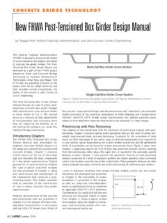
7 From the procedure, information can be derived for pro- portioning of box girder cross-sections. -3- The common configurations of COMPOSITE box girder cross- sections are illustrated in Fig. The top flange of a box girder may be a cast-in-place or precasted reinforced concrete slab. The bottom flange may be a plane or an orthotropic steel plate. The webs may be plain steel plates stiffened transversely or transversely and longitudinally. A COMPOSITE section with a single box and a concrete deck is chosen for this study. A combin- ation of single boxes form a multi-box with the webs carrying the flexural shear and the top deck serving as the roadway. This probably is one of the most efficient and economical arrangements for continuous span COMPOSITE steel-concrete bridges. The procedure developed here for single cell boxes can b"e applied to multi-cell COMPOSITE box GIRDERS .
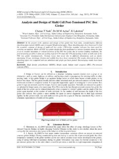
8 In this study a load eccentric to the shear center, as shown in Fig. , is decomposed into bending and torsional systems. The torsional system is further decomposed into pure torsional and distortional systems. The bending system considering shear lag effect is examined in Chapter 2. The concrete deck and the bottom flange can be either isotropic or orthotropic. The expressions for the stress distribution in and the equivalent widths of the flanges are deduced. The pure torsional system is considered in Chapter 3. A unified, consistent method for the'. evaluation of torsional cross-sectional properties of COMPOSITE box sections is presented. In Chapter 4 the distortional system is discussed. The torsional and the distortional warping normal -4- streses are compared~ The deflection caused by cross-sectional distortion is also discussed.
9 In Chapter 5 the computed and the experimental stresses and deflections are compared within the elastic, prebuckling range. Good agreement has been observed. -5- 2 FLEXURAL ANALYSIS . Review of Bending Theory The Bernoulli-Navier hypothesis states that plane cross sections of a flexural member remain plane after bending. This requires that the longitudinal strain of a fiber is proportional to its distance from the neutral axis. For box GIRDERS with high ratios of flange width to span length, shear lag effect in the flanges cannot be ignored. This hypothesis is therefore not valid. A more rigorous solution is required. If the equivalent elastic constants, which are to be discussed in Section , are obtained for the deck of a COMPOSITE box girder as shown in Fig. , the moment of inertia about the centroidal principal axes of a cross section can be computed in the same manner as for conventional COMPOSITE sections.
10 The normal stresses are given by My x cr = ( ). z I. x Mx cr z = .. I. (2. lb). y in which cr is the longitudinal stress, and M , M , I and I are z x y x y the bending moments and moments of inertia of the transformed section about the centroidal principal x- and y-axes, respectively. -6- The shearing stress at a point in the cross section due to a shear force V acting in the y-direction is given by y vy Q. x ,. = ( ). I t. x ~. To compute the static moment of area, Q , a cut must first be intro- x duced to make the cross section of a box girder as shown in Fig.. 2 2 , d eterm1uate. (2. 1). The shear flow in the cut section is V E. vy Q. q o 'U'. =--L. I. JS Y (E~ t i ds) = I. x ( ). x 0 r x The compatibility condition requires that the longitudinal relative movement at the cut be zero, thus requiring a shear flow ql'.