Transcription of Analysis and Design of Multi Cell Post-Tensioned PSC Box ...
1 IOSR Journal of Mechanical and Civil Engineering (IOSR-JMCE) e-ISSN: 2278-1684,p-ISSN: 2320-334X, Volume 12, Issue 4 Ver. VII (Jul. - Aug. 2015), PP 56-64 DOI: 56 | Page Analysis and Design of Multi Cell Post-Tensioned PSC box girder Chetan T Naik1, M Achar2, K Lakshmi3 1M-tech Student, Dept. of Civil Engg., Alpha College of Engineering, Bengaluru, Karnataka, India 2 Associate Vice President, India International Infrastructure Engineers Ltd, Bengaluru, Karnataka, India 3 Assistant Professor, Dept. of Civil Engg., Alpha College of Engineering, Bengaluru, Karnataka, India Abstract: In the present work, Analysis and Design of box girder has been done, consideringtwo different sheathing pipes namely HDPE and corrugated Bright metal pipes. These sheathing pipes have been used to find the economic solution of Design of Multi -cell box girder . CSI- bridge modular software has been used for carrying out Analysis .
2 Multi -cell PSC box girder Design has been performed at various locations along the span so as to consider maximum or critical locations of the PSC box girder due to various loading conditions, the post tensioning of cables is done for jacking load at times the UTS and jacking is done at both ends of the PSC box girder simultaneously., Various losses that occur due to different phenomena such as elastic shortening, Creep, shrinkage, friction and wobble loss have been considered. The results obtained on the two sheathing pipes are compared and are tabulated and graph gas been plotted. Encouraging results have been obtained. Keywords: High density polyethylene (HDPE), Bright metal, Indian road congress (IRC), Pre-stressed concrete (PSC), I. Introduction A bridge or flyover can be defined as a structure including supports erected over a gorge or an obstruction, such as water, highway, or railway, and having a track or passageway for carrying traffic or other moving loads.
3 A box girder bridge is an apparent bridge sector in which main beams contain girders in the hollow box shape. The box girder usually includes either structural steel, pre-stressed concrete or in the form of reinforced concrete or composite section. It is typically trapezoidal, square or rectangular in cross-section. box girder bridges are normally used for bridges, flyovers and at grade separators. Normally pre-stressed box girders are adopted for longer spans only (span range 30 to 90m) due to the fact that pre-stressed concrete box girder the depth of the box girder can be reduced drastically when compared to normal I- girders and the depth of the box girder again depends on the number of webs provided. As the number of web increases the depth of the box girder also reduces. Box girders a most suitable for spans in curved alignment due to their high torsional rigidity. In this present work, one such Multi -cell box girder for a span of 35m has considered.
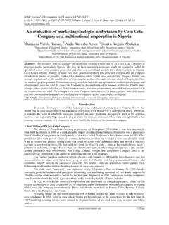
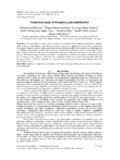
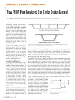
4 Fig 1 shows a schematic representation of Multi cell box girder . longitudinal view of Multi cell box girder II. Literature Review C. Mortensen et., al.,(2003)1presented the paper about the effect of creep, shrinkage Losses in Pre-stressed Concrete Bridges in highly changing Variable Climates in this study is also clarifies about the moist curing after the stressing is also causes in the reduction of the long term losses. P. J. Barret., al.,(2005)2in their paper studied temperature variations effects on precast pre-stressed concrete girders bridges. During manufacturing time and during its service life of pre-stressed girder the effect temperature variations in the girder member can be seen and to calculate exact strains developed in the girders , using of curing with high temperatures during the girder fabrications may cause the thermal expansion in the pre-stressed girders due to the cable which is used for pre-stress is steel due to high temperature elongation of Analysis and Design of Multi Cell Post-Tensioned PSC box girder DOI: 57 | Page cable will occur and loss of pre-stress may occur to overcome this problems using more quantity of steel and concrete quantity if increased in girders it may decreases simultaneously.
5 G. Venkata Siva Reddyet., al., (2014)3presented the paper regarding the response of the box girder bridge based on the moving load Analysis . Models and Analysis has been carried out using FEM based software influence surfaces and influence lines are generalised to analyse the bridge structure subjected to moving loadings with in the lanes on the obtained results some of the conclusions they have drawn that asfor multiple cell box girders are having good resistance in the performance of the box girder . III. Methodology A. Modelling Modelling is carried out using CSI- bridge 2015 (Structural Analysis Programming) software of version this software is basicallyfinite element method software and Finite element method is the most versatile method, which can easily handle structures of complicated shapes, and boundary conditions. It involves subdivision of the whole structure into number of small elements.
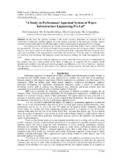
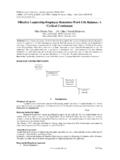
6 Before modelling all the parameters of box girder structure has to be decided based on the IRC standards. In modelling of box girder , main parameter is input of the sizes of box girder and its supporting property and after assigning section property parameter next step part is loading part where lane justification live load application and super imposed dead load application on box girder , different live load application is done to get worst case of live load. In this case, two 70R loading will govern the live loading, once all loading is done Analysis proceedsas per standard practice. Fig 2 shows full view of box girder as a wire mesh model and fig 3 shows the four lane arrangement on the deck of box girder , fig 4 shows 70R vehicle loading arrangement on box girder . Frame element of Multi cell box girder Multi cell box girder with four lane arrangement 70R vehicle loading arrangement Analysis and Design of Multi Cell Post-Tensioned PSC box girder DOI: 58 | Page B.
7 Design The Design of PSC box girder is performed using self-developed spread sheets. The Design is done as per IRC stipulations, the Design procedure comprises of the following units. 1. Calculation of section properties 2. Tabulation of summary of bending moment and shear force 3. Calculation of stress developed due to bending moment and shear force 4. Cable profiling to suit the geometry 5. Calculation of loss of pre-stress due to friction, wobble effect and slip loss 6. Design of end block 7. Calculation of time dependent losses 8. Check for stresses in service and other cases 9. Calculation of temperature stresses 10. Stress check for permissible limit in service case as per IRC 11. Check for deflection 12. Check for ultimate strength 13. Check for ultimate shear strength C. Salient Features Of The Pscbox Girder 1. Type of the structure is Multi cell post tensioned PSC boxgirder 2. Length of box girder = 3. Depth of box girder = 4.
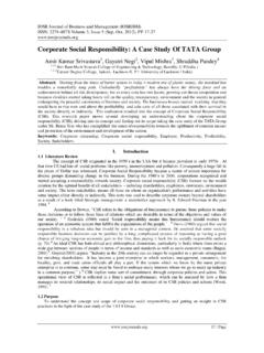
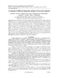
8 Total top width of box girder = 5. Total bottom width of box girder = 6. Thickness of web = (At running section) 7. Thickness of web = (At end section) 8. Thickness of bottom slab = (At running section) 9. Thickness of bottom slab = (At end section) 10. Thickness of top slab = 11. Effective width of top slab = 12. End diaphragm thickness = (2 no s) 13. Mid diaphragm thickness = (2 no s) 14. Number of cells = 2no s 15. Grade of concrete = M45 16. Grade of steel = Fe500 17. Type of strands = 19T15 (main cable ) 18. Type of strands = 19T15 (dummy cable ) 19. Type of sheathing duct = HDPE/Bright Metal 20. Total number of cable used = 18 No s 21. Method of pre-stressing = Post tensioning IV. Results And Discussions A. Bendging Moment And Shear Force Variation of bending moment and shear force in full span for different loading cases is shown in fig 5 and fig dead load the bending moment and shear force value will be more and minimum bending moment and shear force for median, the box girder is analysed as a simply supported and maximum moments will be at midspan and there will be negative moments at supports and maximum shear force at support and there will be minimum shear force at midspan.
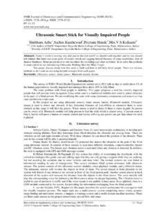
9 Analysis and Design of Multi Cell Post-Tensioned PSC box girder DOI: 59 | Page Bending moment diagram for different loadings Shear force diagram for different loadings B. Displacement Displacement is calculated at the centre of the span for different loading case where the maximum deflection will occur and is tabulated in table 1 and figure 7 shows the deformed shape of box girder for one of the loading case from fig 4 it can be observedthat the deformation pattern on loading of box girder at centre of span the deformation will be more and it will be gradually decrease towards the support, the variations in deformation is shown with specific colours Displacement for Different Loading Case Deformed Shape of box girder -45000-35000-25000-15000-500050000500010 00015000200002500030000 Dead LoadLive LoadCrash Barieerwearing coatMedianDEPTH in mmBending moment in KN-m-6000-4000-2000020004000600005000100 0015000200002500030000 Dead LoadLive LoadCrash BarieerWearing CoatMedianDEPTH in mmShear Forcein and Design of Multi Cell Post-Tensioned PSC box girder DOI.
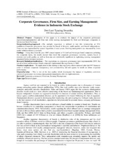
10 60 | Page C. Cable Profile The variation of cable is shown in the fig 8 the arrangement of cable in y-direction and there will be parabolic curve for all set of cables as shown in the fig8 and in fig 9 it is shown that how cables are arranged in box girder at end section an in running all 18no s of main cable are provided in three webs of the box girder and also on the bottom soffit slab of the box girder two emergency cable are provided in the outer web of the box girder , cables provided in the webs will be more effective than the cables provided in the bottom soffit slab. Cable Profile for Half Length of box girder Cable arrangement at End block and Running section D. Elongation Of Cable The total elongation variations in all cables due to pre-stressing is shown in fig the figure it is concluded that HDPE sheathing material have more elongation than the Bright Metal by this we can reduce the pre-stressing force in HDPE and one can achieve an economic Design .