Transcription of 5. Flexural Analysis and Design of Beams 5.1. …
1 CIVL 4135 Flexure845. Flexural Analysis and Design of Reading AssignmentChapter 3 of IntroductionIt is of interest in structural practice to calculate those stresses and deformations which occurin a structure in service under Design load. For reinforced concrete Beams this can be done by themethods just presented, which assume elastic behavior of both materials. It is equally, if not more,important that the structural engineer be able to predict with satisfactory accuracy the ultimatestrength of a structural member. By making this strength larger by an appropriate amount than thelargest loads which can be expected during the lifetime of the structure, an adequate margin of safetyis assured.
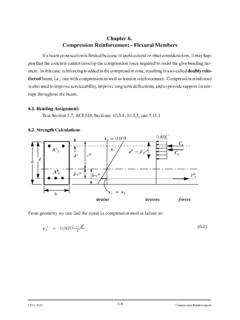
2 Until recent times, methods based on elastic Analysis like those just presented have beenused for this purpose. It is clear, however, that at or near the ultimate load,stresses are no longerproportional to ,closetoultimate,thedistributionofstress esandstrainsisthatoffigure2ratherthat the elastic distribution of stresses and strains given in figure 1 below. More realistic methods ofanalysis,basedonactualinelasticrathert hananassumedelasticbehaviorofthematerial sandresultsmany experimental research, have been developed to predict the ultimate strength.
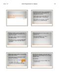
3 Cfc sfs sfsfc c12 CIVL 4135 Flexure85As progressively increasing bending moments are applied to the beam, the strains will increase asexemplified by 1, 2,and 3as shown below. Corresponding to these strains and their linear varia-tion from the neutral axis, the stress distribution will look as shown. 2 1 2 3f1f2f3 StressStrainStress 1 3f1f2f3 CIVL 4135 Flexure86 2 1 2 3f1f2f3 StressStrainStress 1 3f1f2f3f3 CIVL 4135 Flexure87 Cracks, Strains, and Stresses in test beam (From Nawy s Book). Flexure StrengthAs it was mentioned earlier it is important that the structural engineer be able to predict withsatisfactory accuracy the ultimate strength of a structural member.
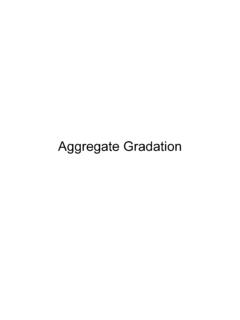
4 It is important to know that at ornear the ultimate load,stresses are no longer proportional to inspection of many concrete stress-strain curves which have been published, showthatthegeometricalshapeofthestressdi stributionisquitevariedanddependsonanumb eroffactorssuch as cylinder strength, the rate, and duration of is a typical stress distribution at the ultimate load. sfsfc uStrainsStressesForcesc cCc= fc bcFigure Strain, Stress, and Force Two Different Types of FailureThere are two possible ways that a reinforced beam can fail: Beam will fail by tension of steelModerate amount of reinforcement is used.
5 Steel yields suddenly and stretches a largeamount, tension cracks become visible and widen and propagate upward (Ductile Fail-ure) Compression failure of concreteLarge amount of reinforcement is used. Concrete fails by crushing when strains becomeso large ( to ). Failure is sudden, an almost explosive nature and occur withno warning ( Brittle Failure).CIVL 4135 Flexure89In a rectangular beam the area that is in compression isbc, and the total compression force on thisarea can be expressed asC=favbc,wherefavis the average compression stress on the areabc.
6 Evi-dently, the average compression stress that can be developed before failure occurs becomes largerthe higher the cylinder strengthfc of the particular concrete. Let =favfc thenCc=favbc= fc bccompression force is applied at c distance from top fiber, andcis the distance of the top on research we have: = fc 4, 0001000 < < = fc 4, 0001000 < < ( )( )FORCESFrom equilibrium we haveCc=Tor fc bc=Asfs( )M=TZ=Asfs(d c)( )orM=CcZ= fc bc(d c)( )CIVL Tension Failurefs=fysteel yielding( )From Eq. ( ) we havec=Asfy bfc dd=Asbdfyd fc = fyfc d ( )Substitutecfrom Eq.
7 ( ) in Eq. ( )Mn=Asfy d fyfc d ( )with the specific, experimentally obtained values for and we always have = forfc =4, 000psi or any other strength( )Therefore, Eq. ( ) simplifies asMn=Asfy d fyfc d ( )orMn= bd2fy 1 fyfc ( )whereMn= nominal moment Compression FailureIn this case, the criterion is that the compression strain in the concrete becomes u= , aspreviously discussed. The steel stressfs, not having reached the yield point, is proportional to thesteel strain, s; according to Hooke s law: u= ( ),andfs<fy( )fs=Es sHooks law, since fs<fy( )CIVL 4135 Flexure91from similar triangles we have uc= sd c s= ud cc( )substitute Eq.
8 ( ) in Eq. ( )fs=Es s=Es ud cc<fy( )From Eq. ( ) we have fc bc=Asfs=AsEs ud cc( )Using Eq. ( ) solve for c, and then findMn,the nominal moment Balance Steel RatioWe like to have tension failure, because it gives us warning, versus compression failurewhich is sudden. Therefore, we want to keep the amount of steel reinforcement in such manner thatthe failure will be of tension steel ratio, brepresents the amount of reinforcement necessary to make a beamfailbycrushingofconcreteatthesameloa dthatcausesthesteeltoyield. Thismeansthatneutralaxismustbelocatedatt heloadwhichthesteelstartsyieldingandconc retestartsreachingitscompressivestrain of u= (ACI )cb= u y+ ud( )T=C Absfy= fc bcb( )Absfy= bbd fy= fc b u u+ yd( ) b= fc fy u u+ y( )CIVL Strain Limits Method for Analysis and Design (ACI 318).
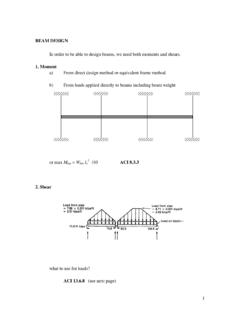
9 In Strain Limits Method, sometime referred to as the Unified Method, the nominal flex-ural strength of a concrete member is reached when the net compressive strain in the extreme com-pression fiber reaches the ACI code-assumed limit of in/in (ACI ). It also hypothesizedthat when the net tensile strain in the extreme tension steel, t= in/in, the behavior is fully duc-tile. The concrete beam sections characterized as Tension-Controlled, with amplewarning of fail-ure as denoted by excessive deflection and , t,issmall,suchasincompressionmem-bers, being equal or less than a Compression-Controlled strain limit, a brittle mode of failure isexpected with a sudden and explosive type of failure.
10 Flexural members are usually tension-con-trolled. However, some sections such as those subjected to small axial loads, but large bending mo-ments, the net tensile strain, t, in the extreme tensile fibers, will have an intermediate or transitionalvalue between the two strain limit states, namely, between the compression-controlled strain limit of t=fyEs=60ksi29, 000ksi= ( )and the tension-controlled strain limit t= in/in. Figure (ACI Figure page 118)shows these three zones as well as the variation in the strength reduction factors applicable to thetotal range of Variation of as a Function of StrainVariationofthe valuefortherangeofstrainbetween t= t= linearly = +( t )(250 3)) ColumnSpiral ( = +( t )(50)) ( ) Variation of as a Function of Neutral Axis Depth Ratio = + 1c dt 53 ColumnSpiral = + 1c dt 53 ( )Figure Example.