Transcription of 5 Guidelines for Gear Unit Selection - SEW-EURODRIVE
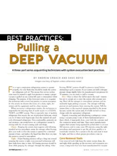
1 38 Catalog Planetary Gearmotors P002 - 082 Series5 Additional documentationGuidelines for Gear Unit Selection5 Guidelines for Gear Unit documentationIn addition to the information in this catalog, SEW-EURODRIVE offers extensive docu-mentation covering the entire topic of electrical drive engineering. This is primarily doc-umentation from the "Drive Engineering Practical Implementation" series. You can or-der the current documentation from SEW-EURODRIVE . The documentation can also bedownloaded in PDF format from the SEW homepage ( ).Drive Engineer-ing Practical ImplementationThe publication "Drive Engineering Practical Implementation Drive Selection withSEW-EURODRIVE Gearmotors" features extensive information on characteristics, dif-ferentiating features and application areas of SEW drives. A comprehensive collectionand assignment of the most important formulae for drive calculation as well as detailedexamples for the most frequently used applications make this documentation an impor-tant tool for project planning and an essential addition to SEW-EURODRIVE Planetary Gearmotors P002 - 082 Series 395 Project planning procedureGuidelines for Gear Unit planning procedureThe following flow diagram illustrates the project planning procedure for a planetary the drive Selection sheet Calculating the basic dataSelecting the application factorsCalculating the requiredrated gear unit torqueSelecting the planetary stageChecking external additional forcesChecking the peak load conditionsChecking the thermal ratingM , , , nPi,F ,F.
2 FMM M MK22K2 SminFStartN2N2K2 maxK2 zul <InquiryStep 1 Step 2 Step 3 Step 4 Step 5 Selecting the motor power rating PMStep 6 Selecting the combination withgearmotor of the "7 Series" / checking M Step 7 Step 8 Step 9 Step 10 Selecting the lubricantStep 11a, exSelecting the accessories Step 12 Technical information for quotation Step 13i40 Catalog Planetary Gearmotors P002 - 082 Series5 Project planning procedureGuidelines for Gear Unit SelectionStep 1: Drive Selection Machine on LSS (normally the driven machine) Ambient temperature [ C] [..] Installation [X]small rooms (v m/s)large rooms and halls (v m/s)outdoors with protection from the sun (v 3 m/s) Ambient conditions [X] Altitude [m] [..] Load Required speed n [1/min] [..] Input power P [kW] [..] Output torque M [kNm] [..] Frequency of peak load (M or P ) [..] Number of starts per hour [.]
3 ] Rotation direction under load (LSS) [X]clockwise (CW)counter-clockwise (CCW)both Operating period/day [X] 3 hours3 .. 10 hours> 10 Backstop required in gear unit [X]NoYe Exact load cycle attached [X]NoYe Machine on HSS (normally the driving machine) Type: [X]AC motorAC motor/inverterDC motorHydraulic Motor power P [kW] [..] Motor torque M [kNm] [..] Input speed n [1/min] [..] If electric motor: [X] [..] IECNEMAM otor size (IEC- or NEMA code) Mounting of motor [X] [..] B3B5V1 Gear unit Gear Unit Type [X]Inline K2 K1 max. MM1 Field of application/industry [..] Application [..] Motor speed n [kW] [..] : [..] = fill in values [X] = make your selections by CWCCWC atalog Planetary Gearmotors P002 - 082 Series 415 Project planning procedureGuidelines for Gear Unit Mounting position [X]M1M2M3 Mounting positions for primary stage RF/KF gearmotors [X]0 90 180 270 Position of motor terminal box and cable entry [X]0 (R)90 (B)180 (L)270 (T)X1230 90 180 270 M4M5M6270 90 180 0 TBX2X31 LRXX0 (R)2X31180 (L) 42 Catalog Planetary Gearmotors P002 - 082 Series5 Project planning procedureGuidelines for Gear Unit Service factor requirements F [X] [.
4 ] Required bearing life L [..] FootFlangeTorque LSS connection to customer machine shaft [X] [..]Elastic coupling (claw or pin type)Flexible coupling Rigid flange couplingBarrel couplingChain Mounting of gear unit housing [X] LSS gear unit design [X] [..]LSS design (if solid shaft) Electrical supply [X] [..]On motor power P / motor torque MOn operating power at LSS P / operating torque at LSS M hoursSolid shaft with keyOtherLSS connection (if hollow shaft)Hollow shaft with keywayOtherHollow shaft for shrink disk connection, shrink disk includedPinionHollow shaft - torque armHollow shaft - foot-mountedHollow shaft - flange-mounted OtherLine voltage V3-phase1-phaseACDCVA uxiliary voltage V3-phase1-phaseACDCVHZD egree of protectionIPExplosions protectionrequiredYe sNoHZS min. K2K2h minMM lineauxSolid shaft without keywaySolid shaft with spline DIN 5480 Hollow shaft with spline DIN Machine shaft bearing2 bearings, gear unit only transmits torque1 bearing opposite to gear unit, gear unit acts as bearing support1 bearing next to gear unit, gear unit acts as bearing Loads on LSS [X] [.
5 ] load F [N]Radial load F [N]Distance from shaft shoulderX [mm]Application angle of radial load [ ] HSS connection to motor [X]Customer installation (foundation base frame)Motor adapter with elastic couplingSwing base/base frameMotor bracket with V-belt drive Motor scoopOther, see sketch FA-+XFR 0 Catalog Planetary Gearmotors P002 - 082 Series 435 Project planning procedureGuidelines for Gear Unit Selection5 Step 2: Calculating the basic data MK2, n2, i, Constant torqueMK2 = Required output torque [Nm]PK1 = Required operating power on HSS [kW]n2 = Output speed (LSS) [rpm]Equivalent torque with load spectrum and constantspeed n2 The following figure shows a load example:MK2 = Operating torque on LSS [Nm]= Time slice of the load I, II,..n = Types of loadGear ration1 = Input speed (HSS) rpmn2 = Output speed (LSS) rpmEfficiency = f (i; Gear unit type)The efficiency of the gear unit is mainly determined by the gearing and bearing friction as well by churning losses.
6 For the calculation, a reference value of 98% is xn29550xComment: If is not known -> = PK1PK1 P M [Nm] t=IMK2equiv(M )K2 ItII+tn(M )K2II+..(M )K2n tN tN tNIIIIIIIVtItIItIIItIV tNMK2MK2MK2MK2MK2MK2equiIIIIIIIV tNtI Planetary Gearmotors P002 - 082 Series5 Project planning procedureGuidelines for Gear Unit SelectionStep 3: Selecting the application factorsFS min - Applica-tion-specific service factorThe application-specific service factor Fs considers the typical load behavior with regardto the drive values with reference to field of application type of driven machine operating time/dayare given in the following service factorFS min see page 45 Peak load factorFF see page 47 Startup factorFStart see page 47 STOPT hese tables apply only to gear units driven by electric motors. For other types of drivemotors, the following correction values apply: Combustion engines with four or more cylinders: FS min ( Selection table) + Combustion engines with one to three cylinders.
7 FS min ( Selection table) + the event of deviations from the typical load behavior, please consult Planetary Gearmotors P002 - 082 Series 455 Project planning procedureGuidelines for Gear Unit Selection5 Field of applicationType of application(Driven machine)Application-specific service factor FS minoperating period / day< 3 h 3-10 h> 10 hWaste water treatmentImpeller and wheel excavators1)1)1)EnergyFrequency wheels (low speed) turbines--1)ConveyorsBucket conveyors - conveyors 100 conveyors > 100 , lifts1)1)1)Rubber and plastic industryExtruders (plastic) (rubber) rollers (two in a row) rollers (three in a row) mills1)1)1)Slab machines1)1)1)Timber industryTimber industry1)1)1)Cranes systemsCranes and hoists2)2)2)Food industryCrushers and production and conveyors, individual drives1)1)1)Table conveyors, group drives1)1)1)Table conveyors, reciprocating1)1)1)Wire drawing )1)1)46 Catalog Planetary Gearmotors P002 - 082 Series5 Project planning procedureGuidelines for Gear Unit SelectionMills and drumsCooling and drying and paper industryDebarking drums and (pick-up, wire drive, wire suction) cylinders (anti-friction bearings) (anti-friction bearings) (pressure and vacuum) and (bark, felt, glue, suction) )1)1)Washer cylinders (dryers)1)1)1)PumpCentrifugal pumps (single-cylinder) pumps (multi-cylinder) pumps (gear type, vane) and mixersAgitators for for liquids (variable density) for solids (non-uniform material) for solids (uniform material) tramways1)1)Surface lifts1)1)1)Continuous aerial tramways1)1)1)Funicular railways1)1)1)FansHeat cooling cooling (axial and radial) ) Consult SEW-EURODRIVE2) Please contact SEW-EURODRIVE .
8 Dimensioning according to FEM1001 Field of applicationType of application(Driven machine)Application-specific service factor FS minoperating period / day< 3 h 3-10 h> 10 hCatalog Planetary Gearmotors P002 - 082 Series 475 Project planning procedureGuidelines for Gear Unit Selection5 Peak load factor - FFThe peak load factor FF takes considers the overload capacity of the gearing and therotating factor - FStartThe startup factor Fstart takes account of the overload caused by 4: Calculating the required nominal gear unit torque MN2 Constant load direction - constant torque:MN2 MK2 x FS min [Nm]Reversing direction of load - constant torque:MN2 MK2 x FS min x [Nm]Planetary gear unit type/sizePeak factor FFFrequency of peak load per > 160 Output shaft as solid shaft shaft with shrink disk con-nection shaft with shrink disk con-nection modeStart factor - FStart )1) Dependent on settingStar / coupling without delay coupling with delay min= Nominal gear unit torque [Nm]= Operating torque at LSS [Nm]= Application-specific service factor MN2MK2FS min= Nominal gear unit torque [Nm]= Operating torque at LSS [Nm]= Application-specific service factor48 Catalog Planetary Gearmotors P002 - 082 Series5 Project planning procedureGuidelines for Gear Unit SelectionStep 5: Selecting the planetary gear unit MN2 The Selection is based on MN2 according to the 6: Selecting the nominal motor power PMStep 7.
9 Selecting the combination with gearmotorExact gear unit reduction ratio iexCheck Ma[1] see PM and planetary stage[2] see Gearmotor Selection / n2 / gear unit ratio iex[3] see Ma > MK2 SizeMN2 [Nm]P00224830P01236810P02251190P03269620 P042100170P052124060P062185660P072245660 P082359400 PMPK1PK2 = Nominal motor power [kW]= Operating power on HSS [kW]= Operating power on LSS [kW]= EfficiencyP=PK2M PK1 [kW]64154 AXX[2][3][2][1]PM[kW]n2Ma[Nm]iexFRa[N]MN 2[Nm]m[kg] [m-1]inCatalog Planetary Gearmotors P002 - 082 Series 495 Project planning procedureGuidelines for Gear Unit Selection5 Step 8: Checking the peak load conditions MK2 zul ; MK2maxPermitted peak output torque MK2 zul:Calculate the peak load MK2 max:* If Fstart is not specified, take account of the start factors according to the table onpage the gear unit Selection :MK2 max MK2 zulStep 9: Check the external additional forcesInfluences and dependencies:The permitted additional forces depend on the following factors.
10 Existing service factor of the gear unit with respect to the Selection data Required bearing life Direction of the axial load (from or towards gear unit) Application angle of the radial force (rotating or at a specific position) Point of force application Ratio between radial and axial force Gear unit mountingMK2 zulMN2FF= Permitted peak output torque [Nm]= Nominal gear unit torque [Nm]= Peak load factorMK2 maxMaFstart= Peak output torque [Nm]= Output torque in relation to motor power [Nm]= Startup factorM=K2 zul2 x MN2FF [kNm]M=K2 maxM x F [Nm]aStart*50 Catalog Planetary Gearmotors P002 - 082 Series5 Project planning procedureGuidelines for Gear Unit SelectionDetermining overhung loadAn important factor for determining the resulting overhung load is the type of transmis-sion element mounted to the shaft end. The following transmission element factors fZhave to be considered for various transmission overhung load exerted on the motor or gear shaft is calculated as follows:Permitted over-hung loadThe basis for determining the permitted overhung loads in the roller bearing calculationis the nominal bearing service life LH10 (according to ISO 281).