Transcription of 5-MW Downwind Wind Turbine Demonstration and …
1 ARTICLESNext-generation energy Solutions Aimed at Symbiosis with the Global Environment1. IntroductionRenewable energy is becoming a major source of energy , surpassing the worldwide facility capacity of coal-fired power generation in 2015(1). In a discussion of energy mix, Japan s Ministry of Economy, Trade and Industry has expressed a goal of helping renew-able energy grow from the market share it had in 2014, to a 22% to 24% share by 2030. Wind power generation accounts for of the market share in Japan(2). One of the challenges facing wind power gen-eration in Japan is to develop wind turbines that are suited to Japan s demanding environment. Offshore models are needed that can withstand typhoons, earthquakes, and lightning strikes(3).To meet this public demand, Hitachi has developed 5-MW wind turbines with enhanced reliability and intended for offshore use.
2 It has also started demon-stration testing of a floating offshore wind Turbine that can be installed in the open ocean to enable more stable and higher-capacity power generation. This article discusses the specifications, characteris-tics, and development of these wind turbines. It looks at the demonstrations being done with Demonstration models and the development being done on floating offshore wind turbines, focusing mainly on control KiyokiKiyoshi Sakamoto, Dr. KakuyaMitsuru SaekiAlready becoming a major source of power around the world, wind power generation is looking ever more promising in Japan in terms of supply stability, environmental suit-ability, and safety. To grow further, providers will need to ensure reliability that meets the needs of installation environments and to offer highly cost-effective wind turbines. This is particularly necessary in coastal waters around Japan, where there is a more demanding environment compared with pioneering wind power areas such as Europe.
3 To address the challenges of the environment, Hitachi has developed 5-MW Turbine models for offshore use. These models are intended for use in areas of different wind speeds, high wind speeds and low wind speeds. Hitachi has completed Demonstration testing of the high-wind-speed model, and has started Demonstration testing of the low-wind-speed model. It is also working on technology for floating offshore wind turbines. This article reports on the development and Demonstration of these technologies with a focus on Turbine control, which will become important for increasing the reliability and cost-effectiveness of these Downwind Wind Turbine Demonstration and Work Toward Smart Operation ControlHitachi Review Vol. 66, No. 5 466 5-MW Downwind Wind Turbines2. 1 Wind Turbine Specifications and CharacteristicsAn overview of the specifications (see Table 1) and concepts(4), (5) of Hitachi s 5-MW wind turbines is given following three main measures are designed to lower costs:(1) A 5-MW wind Turbine power capacity was selected to enable use of the lowest-cost monopile foundation.
4 (2) The nacelle has been made lighter by using a dual-bearing outer ring drive system, reducing the load on the wind Turbine supports.(3) A two-model lineup was developed with the HTW model for use at sites with high aver-age wind speeds and the HTW model for use at sites with low average wind following three main measures are designed to improve reliability:(1) The design extreme wind speed has been set at 55 m/s (10-min average) to withstand the conditions in typhoon-prone areas, and enabling the HTW to withstand a wind speed of 57 m/s (IEC Class T(6)) is within view.(2) Downwind turbines were selected to enable a smooth transition to passive yaw control during storm-induced blackouts, reducing the load and improving reliability during storms.(3) The benefits of Downwind wind turbines have been used to enable a passive cooling system featuring a radiator on the front of the 2 DevelopmentHitachi has conducted several elemental investiga-tions so far, including load tests and lightning tests for the blades, and back-to-back tests and model tests for the drive train.
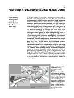
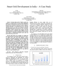
5 Factory testing has also been done to investigate control and vibration character-istics(5), (7). Subsequently, Demonstration testing was performed on a land-based Demonstration model of the HTW for about one year, verifying char-acteristics such as power generation performance and durability(8), (9).In September 2016, Hitachi lengthened the blades of this Demonstration model to create a demonstra-tion model for the HTW It replaced the gearbox with a Japanese-made model at the same time. After test operation, it went into commercial operation in November 2016, and Hitachi is now collecting various types of data from it. The HTW Demonstration model has been confirmed to nearly satisfy the power generation performance initially planned (see Figure 1), and development is approaching its final diameter127 m136 mNumber of blades33 Rotor orientationDownwindDownwindPitch angle 8 deg 8 degOutput controlPitch/variable speedPitch/variable speedConing angle5 deg5 degExtreme wind speed55 m/s55 m/sYearly average wind speed10 m/sTurbulence categoryAAGear ratio1:40 (approx.)
6 1:40 (approx.)GeneratorPermanent magnet synchronous generatorPermanent magnet synchronous generatorPCSFull converterFull converterPCS: power conditioning systemTable 1 HTW and HTW Basic SpecificationsThe HTW was developed for areas of high wind speeds, and the HTW for areas of low wind ,0005,0004,0003,000 Power (kW)2,0001,000005101520 Measured valuesPlanned values25 Wind speed (m/s)Figure 1 HTW Power CurveThe graph shows the correlation between wind speed (at the Turbine hub height of the wind mast) and HTW Demonstration Model3. 1 FRT TestingAs wind power generation has become more wide-spread and gained a greater share of total generated power, wind power providers are (like conventional power providers) being called on to preserve the grid voltage by maintaining power generation dur-ing short-duration grid faults (a capability known as fault ride through, or FRT)(10).
7 Hitachi therefore included a control system to support FRT in the HTW and verified it using the demonstra-tion model. Hitachi s evaluation of the system s elec-trical characteristics has been reported previously(9), (11). This article reports on the control features and a mechanical evaluation of the low-speed shaft rotor (composed mostly of the blades) has a higher moment of inertia than the gen-erator rotor even after accounting for the gear ratio of the gearbox. When a grid fault or similar problem suddenly reduces generator torque, the rotational speed of the entire drive train increases and it starts vibrating at its natural frequency. If the grid voltage is restored and the generator torque increases to its previous level, the drive train s natural vibration acts together with the new torque input to generate a large torque if the timing is poor.
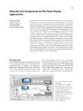
8 The equipment could be damaged as a result, so the following two steps were taken to combat this problem:(1) Mitigating the impact force by preserving as much generator torque as possible during grid faults(2) Reducing vibrations by developing a control method for increasing the torque automatically at the optimum timingThe ratio of residual grid voltage during a grid fault is given as a function of fault time(10). Hitachi used this function to set the test conditions (see Table 2). The most mechanically demanding result was obtained from test No. 8 ( s short-circuit time, 0% voltage ratio, two-phase short circuit) (see Figures 2 to 5) . powerShort-circuit conditionShort-circuit timeResidual voltage ratio1(1) 20% (at low wind speeds)(2) 100% (at high wind speeds) s84% s49% s22% s0%8 Two-phaseFRT: fault ride throughTable 2 FRT Test ConditionsThe conditions were set in accordance with grid connection torque (pu)0 (s)Figure 2 Generator Torque during FRTThe graph shows the measurement values normalized by rating.
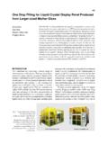
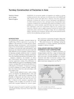
9 A grid fault occurred between the 0 and s rotational speed (pu) 1012345 Time (s)Figure 3 Generator Rotational Speed during FRTThe graph shows the measurement values normalized by sha torque (pu) 1012345 Time (s)Measured valuesReference valuesFigure 4 High-speed Shaft Torque during FRTThe values in the graph have been calculated from the generator s torque and rotational speed, taking transient phenomena into account. The values are normalized by : per unitHitachi Review Vol. 66, No. 5 468 469 FEATURED the grid voltage was restored (at a time of s), the vibrations were reduced by increasing genera-tor torque at times between and s instead of increasing it right away, successfully reducing the torque of the high- and low-speed shafts to within their tolerance 2 Storm StandbyWind Turbine strength design verification requires the use of actual measurements to verify the suitability of loads under the various conditions that the wind turbines are being designed to withstand.
10 The results for the loads during power generation that greatly affect fatigue have previously been reported(8), (9). This article reports on the loads during storm standby that are often critical for static design assumes the following three types of yaw control (control causing the rotor plane to follow the wind direction) during storm standby. This article reports the actual measurement results for type (3).(1) Yaw actuator-driven control when the grid is online (active yaw control)(2) Passive control in Downwind mode during black-outs (passive yaw control)(3) No control when Turbine shuts down abnormallyOn August 22, 2016, Typhoon Mindulle made a near approach to the Demonstration model installa-tion site. An instantaneous maximum wind speed of m/s was observed at the wind mast (90 m high) installed near the wind Turbine , and the wind direction changed from 100 to 200 deg over a period of about 6 h (see Figure 6).