Transcription of 51 & 52 Series II - Fluke
1 51 & 52 Series IIThermometerUsers ManualEnglishSeptember 1999 , 6/01 1999-2001 Fluke Corporation, All rights reserved. Printed in USAAll product names are trademarks of their respective Warranty & Limitation of LiabilityThis Fluke product will be free from defects in material and workmanship for 3 years from the date of purchase. This war-ranty does not cover fuses, disposable batteries or damage from accident, neglect, misuse or abnormal conditions of opera-tion or handling. Resellers are not authorized to extend any other warranty on Fluke s behalf.
2 To obtain service during thewarranty period, send your defective tester to the nearest Fluke Authorized Service Center with a description of the WARRANTY IS YOUR ONLY REMEDY. NO OTHER WARRANTIES, SUCH AS FITNESS FOR A PARTICULARPURPOSE, ARE EXPRESSED OR IMPLIED. Fluke IS NOT LIABLE FOR ANY SPECIAL, INDIRECT, INCIDENTAL ORCONSEQUENTIAL DAMAGES OR LOSSES, ARISING FROM ANY CAUSE OR THEORY. Since some states or countriesdo not allow the exclusion or limitation of an implied warranty or of incidental or consequential damages, this limitation ofliability may not apply to Box 9090 Everett WA98206-9090 Fluke Europe Box 11865602 EindhovenThe NetherlandsTo register your product, visit 10/96iTable of ContentsTitlePageIntroduction.
3 1 Contacting Fluke .. 1 Getting 5 Display Elements .. 7 Using the Thermometer .. 9 Changing Setup 9 Entering or Exiting Setup .. 9 Setup Options .. 9 Changing a Setup 10 Measuring 11 Connecting a Thermocouple .. 11 Displaying Temperatures .. 11 Holding the Displayed Readings .. 12 Viewing the MIN, MAX, and AVG 12 Using the Offset to Adjust for Probe 1251 & 52 Series IIUsers 13 Replacing the Batteries .. 13 Cleaning the Case and 13 Calibration .. 13 Specifications .. 1480 PK-1 Thermocouple (supplied with thermometer).
4 14 Electrical .. 14 Replacement Parts and 15151 & 52 Series IIIntroductionThe Fluke Model 51 and Model 52 Thermometers ( thethermometer ) are microprocessor-based, digitalthermometers designed to use external J-, K-, T-, and E-type thermocouples (temperature probes) as the thermometer only as specified in this , the protection provided by the meter may to safety information in Table 1 and meter symbolsin Table FlukeTo order accessories, receive assistance, or locate thenearest Fluke distributor or Service Center, call:1-888-99- Fluke (1-888-993-5853) in USA1-800-36- Fluke (1-800-363-5853) in Canada+31-402-678-200 in Europe+81-3-3434-0181 in Japan+65-738-5655 in Singapore+1-425-446-5500 from other countriesAddress correspondence to: Fluke CorporationFluke Europe Box Box 1186 Everett, WA 98206-9090 5602 BD EindhovenUSAThe NetherlandsVisit us on the World Wide Web at: To register your product, visit 51 & 52 Series IIUsers Manual2 Table 1.
5 Safety InformationWWarningA Warning identifies conditions and actions that pose hazards to the user. To avoid electrical shock orpersonal injury, follow these guidelines: Before using the thermometer inspect the case. Do not use the thermometer if it appears damaged. Lookfor cracks or missing plastic. Pay particular attention to the insulation around the connectors. Disconnect the thermocouple(s) from the thermometer before opening the case. Replace the batteries as soon as the battery indicator (B) appears. The possibility of false readings canlead to personal injury.
6 Do not use the thermometer if it operates abnormally. Protection may be impaired. When in doubt, have thethermometer serviced. Do not operate the thermometer around explosive gas, vapor, or dust. Do not apply more than the rated voltage, as marked on the thermometer, between the thermocouple(s), orbetween any thermocouple and earth & 52 Series IIIntroduction3 Table 1. Safety Information (cont.)WWarning (cont.) Model 52: Measurement errors may occur if voltages on the measurement surfaces result in potentialsgreater than 1 V between the two thermocouples.
7 When potential differences are anticipated between thethermocouples, use electrically insulated thermocouples. When servicing the thermometer, use only specified replacement parts. Do not use the thermometer with any part of the case or cover Caution identifies conditions and actions that may damage the meter or the equipment under test. Use the proper thermocouples, function, and range for your thermometer. Do not attempt to recharge the batteries. To prevent explosion, do not throw batteries into a fire. Follow local laws or regulations when disposing of batteries.
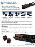
8 Match the + and polarities of the battery with the battery & 52 Series IIUsers Manual4 Table 2. International SymbolsWRefer to the manual for information about with European Union with relevant Canadian StandardsAssociation StartedEverything in this Users Manual applies both to Models51 and 52 unless otherwise become familiar with the thermometer, study thefollowing: Figure 1 and Table 3 describe the components. Figure 2 and Table 4 describe the display. Table 5 describes the functions of the read the following & 52 Series IIGetting Started5 Componentsxx34512 1.
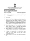
9 ComponentsTable 3. ComponentsAThermocouple T1 inputBModel 52: Thermocouple T2 inputCHolsterDDisplayEButtonsFBattery doorGBatteries51 & 52 Series IIUsers Manual6 Display 2. Display ElementsTable 4. Display ElementsAThe thermocouple measurement includes anoffset. See "Changing Setup Options."BThe displayed readings do not shift function is in is in battery. Replace the 51: T1 52: T1, T2, or T1-T2 temperature Display: MAX, MIN, AVG, or 52: T1or T2 thermocouple Display: The elapsed & 52 Series IIGetting Started7 ButtonsTable 5.
10 ButtonsAPress A to turn the thermometer on or (Shiftfunction)Press G, M (CANCEL) to stop displaying the minimum, maximum, and average readings in thesecondary Q to turn the backlight on and off. The backlight turns off after 2 minutes without any buttonpresses. If the battery is low, the backlight is M to step through the maximum, minimum, and average readings. When viewing loggedreadings, shows the maximum, minimum, and average of the logged G, M (CANCEL) to turn off this C to switch between Celsius (oC), Fahrenheit (oF), and Kelvin (K).