Transcription of 6. PUMPS AND PUMPING SYSTEM - Bureau of Energy …
1 6. PUMPS AND PUMPING SYSTEM113 Bureau of Energy EfficiencySyllabusPumps and PUMPING SYSTEM :Types, Performance evaluation, Efficient SYSTEM opera-tion, Flow control strategies and Energy conservation Pump TypesPumps come in a variety of sizes for a wide range of applications. They can be classifiedaccording to their basic operating principle as dynamic or displacement PUMPS . Dynamicpumps can be sub-classified as centrifugal and special effect PUMPS . Displacement PUMPS canbe sub-classified as rotary or reciprocating PUMPS .
2 In principle, any liquid can be handled by any of the pump designs. Where different pumpdesigns could be used, the centrifugal pump is generally the most economical followed byrotary and reciprocating PUMPS . Although, positive displacement PUMPS are generally moreefficient than centrifugal PUMPS , the benefit of higher efficiency tends to be offset by increasedmaintenance costs. Since, worldwide, centrifugal PUMPS account for the majority of electricity used by PUMPS ,the focus of this chapter is on centrifugal PumpsA centrifugal pump is of a very simple design.
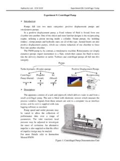
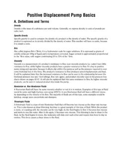
3 The two main parts of the pump are the impellerand the diffuser. Impeller, which is the only moving part, is attached to a shaft and driven by amotor. Impellers are generally made of bronze, polycarbonate, cast iron, stainless steel as wellas other materials. The diffuser (also called as volute)houses the impeller and captures and directs the wateroff the impeller. Water enters the center (eye) of the impeller and exitsthe impeller with the help of centrifugal force. As waterleaves the eye of the impeller a low-pressure area is cre-ated, causing more water to flow into the pressure and centrifugal force cause this tohappen.
4 Velocity is developed as the water flows throughthe impeller spinning at high speed. The water velocity iscollected by the diffuser and converted to pressure byspecially designed passageways that direct the flow tothe discharge of the pump, or to the next impeller shouldthe pump have a multi-stage configuration. The pressure (head) that a pump will develop is indirect relationship to the impeller diameter, the numberof impellers, the size of impeller eye, and shaft speed. Capacity is determined by the exit widthof the impeller.
5 The head and capacity are the main factors, which affect the horsepower size ofthe motor to be used. The more the quantity of water to be pumped, the more Energy is required. Figure Centrifugal pumpA centrifugal pump is not positive acting; it will not pump the same volume always. Thegreater the depth of the water, the lesser is the flow from the pump. Also, when it PUMPS againstincreasing pressure, the less it will pump. For these reasons it is important to select a centrifu-gal pump that is designed to do a particular job.
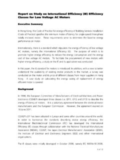
6 Since the pump is a dynamic device, it is convenient to consider the pressure in terms ofhead meters of liquid column. The pump generates the same head of liquid whatever thedensity of the liquid being pumped. The actual contours of the hydraulic passages of theimpeller and the casing are extremely important, in order to attain the highest efficiency possi-ble. The standard convention for centrifugal pump is to draw the pump performance curvesshowing Flow on the horizontal axis and Head generated on the vertical axis.
7 efficiency , Power& NPSH Required (described later), are conventionally shown on the vertical axis, plottedagainst Flow, as illustrated in Figure PUMPS and PUMPING System114 Bureau of Energy EfficiencyFigure Pump Performance CurveGiven the significant amount of electricity attributed to PUMPING systems, even smallimprovements in PUMPING efficiency could yield very significant savings of electricity. Thepump is among the most inefficient of the components that comprise a PUMPING SYSTEM , includ-ing the motor, transmission drive, piping and valves.
8 Hydraulic power, pump shaft power and electrical input powerHydraulic power Ph= Q (m3/s) x Total head, hd- hs(m) x (kg/m3) x g (m/s2) / 1000 Where hd discharge head, hs suction head, density of the fluid, g acceleration due to gravityPump shaft power Ps= Hydraulic power, Ph / pump efficiency , PumpElectrical input power= Pump shaft power Ps SYSTEM CharacteristicsIn a PUMPING SYSTEM , the objective, in most cases, is either to transfer a liquid from a source toa required destination, filling a high level reservoir, or to circulate liquid around a SYSTEM .
9 As a means of heat transfer in heat pressure is needed to make the liquid flow at the required rate and this must overcomehead 'losses' in the SYSTEM . Losses are of two types: static and friction head. Static head is simply the difference in height of the supply and destination reservoirs, as inFigure In this illustration, flow velocity in the pipe is assumed to be very small. Anotherexample of a SYSTEM with only static head is PUMPING into a pressurised vessel with short piperuns. Static head is independent of flow and graphically would be shown as in Figure PUMPS and PUMPING System115 Bureau of Energy EfficiencyFigure Friction Head vs.
10 FlowFigure Static HeadFigure Static Head vs. FlowFriction head (sometimes called dynamic head loss) is the friction loss, on the liquid beingmoved, in pipes, valves and equipment in the SYSTEM . Friction tables are universally available forvarious pipe fittings and valves. These tables show friction loss per 100 feet (or metres) of a spe-cific pipe size at various flow rates. In case of fittings, friction is stated as an equivalent lengthof pipe of the same size. The friction losses are proportional to the square of the flow rate.