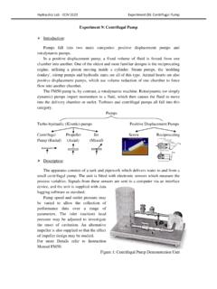
Transcription of SUBMERSIBLE PUMP SELECTION - National Pump Company
1 260 SUBMERSIBLESA GORMAN-RUPP COMPANYSUBMERSIBLE PUMP SELECTIONA SUBMERSIBLE pump consists of the following basic elements: < Bowl Assembly < Motor < Cable < Drop Pipe < Surface Plate (with)(without) discharge elbowDATA REQUIRED FOR SELECTION < Capacity in GPM < Static and Pumping Levels in Well < Setting Required (drop pipe) < Well Diameter < Electric CharacteristicsDETERMINATION OF TOTAL HEADT otal head = H + P + F where: H = Distance from surface to water level when pumping P = Pressure (head) at pump discharge F = Drop pipe friction (+) check valve(s) lossBOWL ASSEMBLY SELECTIONS elect impeller in exactly the same manner as for lineshaft type pump. Note comments under WELL PIPE SELECTIONSize of drop pipe is selected based on the capacity to be pumped.
2 SUBMERSIBLE pumps frequently require smaller drop pipe than do line shaft pumps since the full area of the pipe is used to deliver water to the velocity in drop pipe should not be less than recommend drop pipe size be selected to limit the maximum friction loss to 5 per 100 of pipe. SELECTION table is based upon this limitation. Smaller size drop pipe may be used when bowl assembly and motor are adequate for operation with the increased head and furnished by others must be standard pipe with 3/4 taper NPT threading throughout and to connect to the bowl assembly and surface VALVESW here total head exceeds 200 , the use of a drop pipe check valve is recommended. Check valve should be located approximately 20 above the bowl assembly.
3 For settings over 600 , the use of two check valves are recommended, with the first valve approximately 100 above bowl unit and the second located approximately 60% of the distance between the first valve and the surface GORMAN-RUPP COMPANYSUBMERSIBLE PUMP SELECTION (CONT.)CABLE SELECTIONS elect a drop cable designed for use in water. The insulation on the conductors should be RW, RUW, TW, or their equivalent. DO NOT compromise on drop cable quality. Paying a little more will save you money in the long run. Cable SELECTION chart is based on horsepower, voltage, and length of cable required. Cable sizes and lengths are maximum allowable. Higher operating efficiency will be obtained by using the next larger cable size when lengths approach listed limits.
4 All size and cable lengths shown are for copper wire : Use of smaller cable than recommended will void cable length equal to length of setting plus an additional 10 or more to connect to starter at the surface, plus 1 additional foot for each 50 of length in the well to compensate for unavoidable slack in the PLATES urface place consists of flat steel plate with connection for drop pipe, hole for entrance of cable, vent hole, hole for air line or water level gauge. Surface plate is supplied (with)(without) elbow. If elbow is furnished, it can be flanged or female thread. Surface plate is selected to match drop pipe SELECTIONM otor SELECTION is based upon horsepower required, pump RPM, thrust load, well diameter, and power supply.
5 Also, see comments under WELL SIZE and WATER EQUIPMENTS electing the proper overload protection is one of the most important factors in obtaining a successful SUBMERSIBLE installation. SUBMERSIBLE motor starters should provide the following: < Positive motor protection against single phasing. < Positive motor protection against sustained overload in excess of 115% of motor rating. < Motor protection if rotor is stalled. < Tripping timers independent of ambient temperature; (Ambient Compensated Quick Trip Heaters).NOTE: Failure to provide quick trip overload heaters will void , note that under certain conditions of maximum load on the motor (use of the service factor), a starter one size larger may be PROTECTIONL ightning and power surge damage are major causes of SUBMERSIBLE motor failures, so a three-phase lightning arrestor is a must.
6 The arrestor is mounted in the pump panel and grounded to both ground terminals onto pump panel and well head. If you use plastic pipe, the ground wire should also be connected to a stud on the motor to obtain good grounding and maximum benefit from the : Failure to ground this unit may result in serious electrical shock. A faulty motor or wiring can be a serious electrical shock hazard if it is accessible to human contact. To avoid this danger, connect the motor frame to the power supply grounding terminal with copper conductor no smaller than the circuit conductors. In all installations, connect above ground metal plumbing to the power supply ground per National Article 250-80 to prevent shock GORMAN-RUPP COMPANYSELECTION PROCEDURE EXAMPLEREQUIREMENTS: GPM Feet Pumping Feet Well Inside Diameter Power Ph.
7 / 60 Hertz / 480 Volts Pumping WaterDETERMINE TOTAL DYNAMIC HEAD: (TDH) = pumping level + head required + drop pipe friction loss + check valve(s) friction TDH = a. Pumping ..200 Feet b. Head Feet c . 8 drop pipe friction head for 850 GPM is feet per 100 feet. 200 feet of new 8 drop pipe has a total loss of x =.. Feet d. Friction head loss in one 8 check valve =.. Feet TOTAL Dynamic Head (TDH).. Feet2. IMPELLER SELECTION : Since no speed was specified, use 3450 RPM. The S9 XHC shows 76% efficiency , full diameter. a. Number of stages required = No. Stg. = TDH = = USE 3 stages, Head/Stage 125 b. Total Pump Thrust = TDH x Impeller Thrust Factor x Sp.
8 Gr. + (Rotor weight per stage x number of stages) ( x x 1) + ( x 3) = c. Bowl Horsepower = GPM x TDH x Sp. Gr. = 850 x x 1 = BHP 3960 x Bowl Eff. 3960 x d. Pump efficiency = GPM x TDH x Sp. Gr. = 850 x x 1 = 3960 x Bowl 3960 x GORMAN-RUPP COMPANYSELECTION PROCEDURE EXAMPLE (CONT.)3. MOTOR SELECTION : a. Bowl Horsepower = b. Pump Operating Speed = 3450 RPM c. Total Pump Thrust = d. 3 Phase, 60 Hertz, 460 Volts (nameplate) e. Thrust Bearing Loss = .10 x Total Pump Thrust = .10 x = .17 1000 1000 f. Horsepower Loss in Cable: Total Cable Length = 200 feet + 10 + 4 = 214 feet Select #00 cable from SELECTION Chart 100 motor current = 130 amps full load Horsepower loss in #00 cable = loss per 100 x Total Cable Length =.
9 65 x 214 = 100 100 g. Total Horsepower: = Bowl horsepower + Thrust HP loss + Cable horsepower loss = + + .17 = (100 motor OK to use.)4. CABLE SELECTION : a. Determine total cable length. Total Cable Length = Pumping Level + Surface Length + Slack = 200 + 10 + 4 = 214 feet b. Per Cable SELECTION Chart @ 460 volts horsepower, use #00 SURFACE PLATE: Use 8 surface CHECK VALVE: One 8 check valve required. 7. CALCULATION OF FIELD PERFORMANCE: To determine field head and overall pump efficiency : a. Field Head = laboratory head minus total friction loss. (1) Total friction loss = loss in drop pipe + check valve(s) b. Overall Pump efficiency = Water HP x (motor eff.)
10 % - cable loss %) Laboratory c. Water Horsepower = GPM x Head 3960 d. Laboratory Horsepower = GPM x Head x Sp. Gr. 3960 x Pump for other values of power consumption can be carried out per equations noted below: e. Wire to Water efficiency - same as Overall efficiency . f. Input Horsepower = Pump Brake Horsepower Motor efficiency - Cable Loss g. Wire to Water Horsepower = Same as Input Horsepower h. Kilowatt Hours per 100 Gallons = Field head x .00314 Overall efficiency i. Kilowatts Input = Input Horsepower x j. Gallons per Kilowatt Hour = Overall efficiency x 1000 Field Head x.