Transcription of 65-0229 - 7800 SERIES Relay Modules
1 Registered TrademarkCopyright 1998 Honeywell Inc. All Rights ReservedCHECKOUT AND TEST65-0229-17800 SERIESR elay ModulesThis publication provides general checkout and troubleshooting procedures for the 7800 SERIES Relay CHECKOUTIMPORTANTP erform all Static Checkout Procedures in theapplicable Relay module installation instructionsbefore starting these cause serious injury or not allow fuel to accumulate in the combustionchamber for longer than a few seconds withoutigniting to prevent danger of forming explosive mixtureClose manual fuel shutoff valve(s) if flame is notburning at end of specified Shock cause serious injury or extreme care while testing system. Linevoltage is present on most terminal connectionswhen power is master switch before removing or installing7800 SERIES Relay module or Keyboard DisplayModule sure all manual fuel shutoff valve(s) are closed beforestarting initial lightoff check and Pilot Turndown not put the system in service until you have satisfactorilycompleted all applicable tests in this section and any othersrecommended by the original equipment trial for pilot to ten seconds.
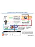
2 Limit the attempt to lightmain burner to two seconds after fuel reaches burner not exceed manufacturer nominal lightoff Malfunction or Damage Relay module type is unique. Using existingwiring on a Relay module change can causeequipment wiring changes when a Relay module is replacedwith a different 7800 SERIES Relay module tosequence the system fails to perform properly, note thefault code, fault message, equipment status, andsequence time on the display. Then refer to theTroubleshooting all required Checkout tests after alladjustments are made. All tests must be satisfiedwith the flame detector(s) in their final RecommendedS7800A Keyboard Display ModuleVolt-ohmmeter (1M ohm/volt minimum sensitivity) with:0-300 Vac ohm Vdc SummaryTable 1 provides an overview of checkout steps performed foreach applicable Installation Instructions for location of component partsand/or Q7800 Specifications for terminal SERIES Relay MODULES65-0229 1 Table 1.
3 Checkout Steps and Applicable 7800 SERIES StepPilotedSystemsDSI SystemsInfrared FlameDetectorsFlame RodSystemsUltraviolet FlameDetectorsPreliminary InspectionXXXXXF lame Signal MeasurementXXXXXI nitial Lightoff Check forProved PilotXInitial Lightoff Check forDirect Spark IgnitionXPilot Turndown TestXIgnition Interference TestXHot Refractory SaturationTestXHot Refractory Hold-inTestXXXX XIgnition Spark PickupXResponse to OtherUltraviolet SourcesXFlame Signal with HotCombustion ChamberXXXX XSafety Shutdown TestsXXXXXP reliminary InspectionPerform the following inspections to avoid common certain that:1. Wiring connections are correct and all terminal screwsare Flame detector(s) is clean, installed and positionedproperly. Consult the applicable Combination of amplifier and flame detector(s) iscorrectly used. See the amplifier Plug-in amplifier and purge card (if required) aresecurely in Burner is completely installed and ready to fire; consultequipment manufacturer instructions.
4 Fuel lines arepurged of Combustion chamber and flues are clear of fuel andfuel Power is connected to the system disconnect switch(master switch).8. Lockout is reset (reset button) only if the Relay Moduleis Run/Test Switch (if present) is in RUN System is in STANDBY condition. STANDBY messageis displayed in the S7800 Keyboard Display All limits and interlocks are Signal MeasurementSee instructions provided with the LIGHTOFF CHECKSP roved Pilot SystemsPerform this check on all installations that use a pilot. Itshould immediately follow the preliminary : Low fuel pressure limits, if used, could be open. If so,bypass them with jumpers during this the master sure that the manual main fuel shutoff valve(s) isclosed. Open the manual pilot shutoff valve. If the pilottakeoff is downstream from the manual main fuelshutoff valve(s), slightly open the manual main valve tosupply pilot gas flow. Make sure the main fuel is shut offjust upstream from the burner inlet, or disconnect powerfrom the automatic main fuel valve(s).
5 The master switch and start the system with a callfor heat by raising the setpoint of the operatingcontroller, see the Relay module sequence. The 7800 SERIES Relay module should start the the sequence advance to PILOT IGN (status isdisplayed on the Keyboard Display module , if used),PILOT LED turns on, ignition spark should occur andthe pilot should light. If the pilot ignites, the FLAME LEDis energized. Go to step the pilot flame is not established in ten seconds (fourseconds if configuration jumper JR1 is clipped), safetyshutdown occurs. Let the sequence complete its the reset pushbutton, and let the system recycleonce. If the pilot still does not ignite, make the followingignition/pilot the master switch and remove the 7800 SERIES Relay module from the SERIES Relay MODULES365-0229 the subbase, jumper L1 to the ignitionterminal; refer to the appropriate wiring diagramto determine the proper terminal. Disconnect theleadwire to the pilot valve if it is connected to thesame the master switch to energize only theignition the ignition spark is not strong and continuous,open the master switch and adjust the ignitionelectrode spark gap setting to the sure the ignition electrodes are the master switch and observe the a continuous spark is obtained, open themaster switch and add a jumper on the subbasefrom terminal L1 power to the pilot terminal 8 or21.
6 Reconnect the leadwire from the pilot valve ifit was disconnected in step the master switch to energize both theignition transformer and the pilot the pilot does not ignite and if the ignition sparkis still continuous, adjust the pressure regulatoruntil a pilot is the pilot ignites properly and stays ignited,open the master switch and remove the jumper(s)from the terminals of the for adequate bleeding of the fuel the 7800 SERIES Relay module on thesubbase, close the master switch, and then returnto step pilot ignites, measure the flame signal. If the pilotflame signal is unsteady or approaching the Vdcminimum value, adjust the pilot flame size or detectorsighting to provide a maximum and steady flame the system to recheck lightoff and pilot the MAIN LED turns on, make sure the automaticmain fuel valve is open; then smoothly open the manualmain fuel shutoff valve(s) and watch for main burnerflame ignition. When the main burner flame isestablished, go to step the main burner flame is not established within fiveseconds or the normal lightoff time as specified by theequipment manufacturer, close the manual main fuelshutoff valve(s).
7 The system to recheck the lightoff and pilotflame open the manual fuel shutoff valve(s) and trylightoff again. (The first re-attempt may have beenrequired to purge the lines and bring sufficient fuel tothe burner.) the main burner flame is not established within fiveseconds or the normal lightoff time specified by theequipment manufacturer, close the manual main fuelshutoff valves(s). Check all burner the main burner flame is not established after twoattempts:A. Check for improper pilot Check for excess combustion air at low Check for adequate low fire fuel Check for proper gas supply Check for proper valve for proper pilot flame steps 8 and 9 to establish the main burnerflame; then go to step the sequence in RUN, make burner adjustmentsfor flame stability and Btu input down the system by opening the burner switch orby lowering the setpoint of the operating sure the main flame goes out. There may be adelay due to gas trapped between the valve(s) andburner.
8 Make sure all automatic fuel valve(s) the system by closing the burner switch and/orraising the setpoint of the operating controller. Observethat the pilot is established during PILOT IGN and themain burner flame is established during MAIN IGNwithin the normal lightoff the flame signal. Continue to check for theproper signal through the RUN period. Check the signalat both High and Low Firing Rate positions and whilemodulating, if the burner through another sequence, observingthe flame signal flame and main flame flame alone (unless monitoring anintermittent pilot). Also observe the time it takesto light the main flame. Ignition of main flameshould be sure all readings are in the required rangesbefore the system to normal : After completing these tests, open the master switchand remove all test jumpers from the subbaseterminals, limits/controls or Spark Ignition SystemsThis check applies to gas and oil burners not using a pilot.
9 Itshould immediately follow the preliminary inspection. Refer tothe appropriate sample block diagram of field wiring for theignition transformer and fuel valve(s) : Low fuel pressure limits, if used, could be open. If so,bypass them with jumpers during this the master the normal ready-to-fire checkout of the fuelsupply and equipment as recommended by theequipment all manual main fuel shutoff valve(s). Check thatthe automatic fuel valve(s) is closed. Make sure fuel isnot entering the combustion the master switch and start the system with a callfor heat by raising the setpoint of the operatingcontroller; see the Relay module sequencing. Theprogram sequence should start the INITIATE the sequence advance through PREPURGE (ifapplicable). Ignition spark should occur when the PILOTLED turns on. Listen for the click of the first stage fuelsolenoid valve(s). The Relay module locks out and theALARM LED turns the 7800 SERIES Relay module complete its the manual fuel shutoff valve(s).
10 The reset button and the Relay module recycles theprogram sequence through PREPURGE (if applicable). the PILOT LED turns on, make sure that the firststage burner flame is established. If it is, go to step the first stage burner flame is not established withinfour seconds, or within the normal lightoff time specifiedby the equipment manufacturer, close the manual fuelshutoff valve(s), and open the master all burner SERIES Relay MODULES65-0229 about three minutes. Close the master switch,open the manual fuel shutoff valve(s), and try to light offthe burner again. The first attempt may be required topurge the lines and bring sufficient fuel to the the first stage burner flame is not established withinfour seconds, or within the normal lightoff time specifiedby the equipment manufacturer, close the manual fuelshutoff valve(s), and open the master necessary, repeat steps 11 through 13 to establishthe first stage burner flame. Then go to step the first stage burner flame is established, thesequence advances to RUN.