Transcription of 690 ARTICLE Solar Photovoltaic (PV) Systems
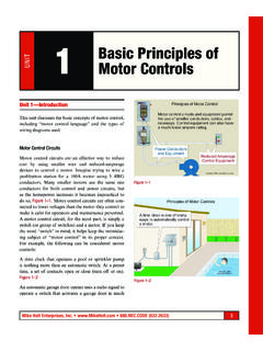
1 Mike Holt Enterprises, Inc. ( )247 ARTICLES olar Photovoltaic (PV) Systems690 PART I. 690 applies to Photovoltaic (PV) electrical energy Systems , array circuit(s), inverter(s), and charge controller(s) for PV Systems , which may be interactive with other electrical power sources (elec-tric utility) or stand-alone with or without energy storage (batteries). Figures 690 1 and 690 Definitions. Alternating-Current PV Module. A PV module unit consisting of Solar cells, inverter, and components necessary to generate alternating-current (ac) power when exposed to sunlight. Figure 690 3 INTRODUCTION TO ARTICLE 690 Solar Photovoltaic (PV) SYSTEMSYou ve seen, or maybe own, photocell-powered devices such as night lights, car coolers, and toys.
2 These generally consist of a small Solar panel and a small light or motor. Typically, these run on less than 10V dc and draw only a fraction of an ampere. These kinds of devices are very different from a system that can power a house or interconnect with a utility to offset a building s energy the sheer size and weight of Solar modules for providing electrical power to a building. You re looking at mechanical and site selec-tion issues that may require specialized expertise. The value of these modules also means there are security issues to consider, which may require more than just installing locks. There are also civil and architectural issues to summary, these installations are complicated and require expertise in several non-electrical areas, which the NEC doesn t 690 focuses on reducing the electrical hazards that may arise from installing and operating a Solar Photovoltaic system, to the point where it can be considered safe for property and ARTICLE consists of eight Parts, but the general requirements of Chapters 1 through 4 apply to these installations, except as specifically modified by ARTICLE 690 1 Mike Holt Enterprises, Inc.
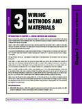
3 ( )253 Solar Photovoltaic (PV) : Grouping isn t required if the PV circuit enters from a cable or raceway unique to the circuit that makes the grouping obvious.(C) Module Connection. Module connections must be arranged so that the removal of a module doesn t interrupt the grounded conduc-tor to other PV source circuits.(D) Equipment. Equipment for PV Systems such as inverters, pho-tovoltaic modules, source-circuit combiners, and charge controllers must be identified and listed for the application. Figure 690 Installation.(A) Solar Photovoltaic System. A PV system is permitted to supply power to a building/structure in addition to any other electricity supply system(s).
4 (B) Identification and Grouping. PV system conductors, both dc and ac, can be installed in the same raceways, outlet and junction boxes, or similar fittings with each other, but must be kept entirely indepen-dent of non-PV system wiring conductors. Figure 690 22PV system conductors must be identified by separate color coding, marking tape, tagging, or other approved means and grouped as follows:(1) PV Source Circuits. Identified at points of termination, connec-tion, and splices.(2) PV Output and Inverter Circuits. Identified at points of termina-tion, connection, and splices.(3) Multiple Systems . Conductors of each system must be identified at termination, connection, and splice points.
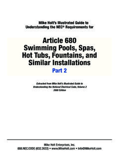
5 Figure 690 23Ex: Identification of different Systems isn t required where conductor identification is evident by spacing or arrangement.(4) Grouping. Where the conductors of more than one PV system occupy the same junction box or raceway with removable cover, the ac and dc conductors of each system must be grouped together by cable ties and at intervals not to exceed 6 ft. Figure 690 24 Figure 690 22 Figure 690 24 Figure 690 23254 Mike Holt s Illustrated Guide to Understanding 2011 NEC Requirements for Solar Photovoltaic Photovoltaic (PV) Systems (F) Circuit Routing. PV source and output conductors must be routed along building structural members (beams, rafters, trusses, and col-umns) where the location of those structural members can be deter-mined by location of PV source and output conductors imbedded in built-up, laminate, or membrane roofing materials in areas not covered by PV modules and associated equipment must be clearly marked.
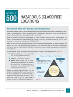
6 (H) Multiple Inverters. Where multiple utility-interactive inverters are located remote from each other, a directory is required at each dc PV system disconnecting means, at each ac disconnecting means, and at the main service disconnecting means showing the location of all ac and dc PV system disconnecting means in the : A directory isn t required where all PV system disconnecting means are grouped at the service disconnecting Ground-Fault Protection. PV Systems must have ground-fault protection to reduce fire hazards. Figure 690 27(C) Labels and Markings. A warning label must be on the utility-interactive inverter stating the following: Figure 690 28 WARNING ELECTRIC SHOCK HAZARD IF A GROUND FAULT IS INDICATED, NORMALLY GROUNDED CONDUCTORS MAY BE UNGROUNDED AND ENERGIZEDA uthor s Comment: Listing means that the equipment is in a list published by a testing laboratory acceptable to the authority having jurisdiction [ ARTICLE 100].
7 (E) Qualified Persons. PV Systems , associated wiring, and intercon-nections must be installed by a qualified person. Figure 690 26 Note: A qualified person has the knowledge related to construction and operation of PV equipment and installations; along with safety training to recognize and avoid hazards to persons and property [ ARTICLE 100].Figure 690 27 Figure 690 25 Figure 690 26 Mike Holt Enterprises, Inc. ( )255 Solar Photovoltaic (PV) (B) Inverter Output Circuit. The output circuit conductors of an ac module are considered an Inverter Output Circuit as defined in Figure 690 30 PART II. CIRCUIT Maximum Voltage(A) Maximum PV System Voltage.
8 Maximum PV system voltage is equal to the sum of the rated open-circuit voltage (Voc) of the series-connected PV modules as corrected for the lowest-expected ambient temperature in accordance with Table voltage temperature coefficients supplied in the instruc-tions for PV modules must be used to calculate the maximum PV system voltage instead of Table Figure 690 31 Note: One source for lowest-expected ambient tempera-ture is the Extreme Annual Mean Minimum Design Dry Bulb Temperature found in the ASHRAE Handbook Fundamentals. See s Comment: PV module voltage has an inverse relation-ship with temperature, which means that at lower temperatures, PV modules voltage raises and at higher temperatures, PV mod-ules voltage falls from its nameplate : The label must resist the environment for 25 to 40 years of system use and be suitable for the environment and be installed so as not to void equipment listing [ (B)].
9 When plastic is used, it should not be placed in direct sunlight, unless specifically manufactured as sun-light resistant; a metallic engraved sign would be Alternating-Current Modules.(A) PV Source Circuits. ARTICLE 690 requirements pertaining to dc PV circuits don t apply to ac PV modules since ac PV modules have no dc output. Figure 690 29 Figure 690 29 Figure 690 30 Figure 690 28256 Mike Holt s Illustrated Guide to Understanding 2011 NEC Requirements for Solar Photovoltaic Photovoltaic (PV) SystemsPV System Voltage Based on Manufacturer Temperature Coefficient %/ CExample: Using the manufacturer s temperature coefficient C, what s the maximum PV source circuit voltage for twenty-three modules each rated Voc , at a cell tempera-ture of -7 C?
10 Figure 690 33PV Voc = Rated Voc {1 + [(Min. Temp. C - 25 C) Module Coefficient %/ C]} # Modules per Series StringPV Voc = Voc {1+ [(-7 C - 25 C) C]} 23 modulesPV Voc = Voc {1 + [-32 C C]}) 23 modulesPV Voc = Voc {1 + } 23 modulesPV Voc = Voc 23 modulesPV Voc = 571 VTable Voltage Correction FactorsLowest-Expected Ambient Temperature C FTemperature Correction Factor0 to 432 to to -523 to to -1014 to to -155 to to -204 to to -25-5 to to -30-14 to to -35-23 to to -40-32 to : Using Table , what s the maximum PV source circuit voltage for twenty-three modules each rated Voc , at an ambient temperature of -7 C?