Transcription of 7-1 Chapter 7- Memory System Design Chapter 7- Memory ...
1 7-1 Chapter 7- Memory System DesignComputer Systems Design and Architecture by V. Heuring and H. Jordan 1997 V. Heuring and H. Jordan: Updated David M. Zar, February, 2001 Chapter 7- Memory System Design Introduction RAM structure: Cells and Chips Memory boards and modules Two-level Memory hierarchy The cache Virtual Memory The Memory as a sub- System of the computer7-2 Chapter 7- Memory System DesignComputer Systems Design and Architecture by V. Heuring and H. Jordan 1997 V. Heuring and H. Jordan: Updated David M. Zar, February, 2001 IntroductionSo far, we ve treated Memory as an array of words limited in size only by the number of address bits. Life is seldom so world issues arise: cost speed size power consumption volatility other issues can you think of that will influence Memory Design ?7-3 Chapter 7- Memory System DesignComputer Systems Design and Architecture by V.
2 Heuring and H. Jordan 1997 V. Heuring and H. Jordan: Updated David M. Zar, February, 2001In This Chapter we will cover Memory components: RAM Memory cells and cell arrays Static RAM more expensive, but less complex Tree and Matrix decoders needed for large RAM chips Dynamic RAM less expensive, but needs refreshing Chip organization Timing ROM Read only Memory Memory Boards Arrays of chips give more addresses and/or wider words 2-D and 3-D chip arrays Memory Modules Large systems can benefit by partitioning Memory for separate access by System components fast access to multiple words more 7-4 Chapter 7- Memory System DesignComputer Systems Design and Architecture by V. Heuring and H. Jordan 1997 V. Heuring and H. Jordan: Updated David M. Zar, February, 2001In This Chapter we will also cover The Memory hierarchy: from fast and expensive to slow and cheap Example: Registers->Cache >Main Memory ->Disk At first, consider just two adjacent levels in the hierarchy The Cache: High speed and expensive Kinds: Direct mapped, associative, set associative Virtual Memory makes the hierarchy transparent Translate the address from CPU s logical address to thephysical address where the information is actually stored Memory management - how to move information back and forth Multiprogramming - what to do while we wait The TLB helps in speeding the address translation process Overall consideration of the Memory as a 7- Memory System DesignComputer Systems Design and Architecture by V.
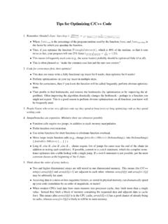
3 Heuring and H. Jordan 1997 V. Heuring and H. Jordan: Updated David M. Zar, February, 2001 Fig. The CPU Main Memory InterfaceSequence of events:Read:1. CPU loads MAR, issues Read, and REQUEST2. Main Memory transmits words to MDR3. Main Memory asserts :1. CPU loads MAR and MDR, asserts Write, and REQUEST2. Value in MDR is written into address in Main Memory asserts memoryAddress busData bussAddress01232m 1A0 Am 1D0 Db 1R/WREQUESTCOMPLETEMDRR egisterfileControl signalsmwwMARb7-6 Chapter 7- Memory System DesignComputer Systems Design and Architecture by V. Heuring and H. Jordan 1997 V. Heuring and H. Jordan: Updated David M. Zar, February, 2001 The CPU Main Memory Interface -cont' points: if b<w, Main Memory must make w/b b-bit transfers. some CPUs allow reading and writing of word sizes < : Intel 8088: m=20, w=16,s=b= and 16-bit values can be read and written If Memory is sufficiently fast, or if its response is predictable,then COMPLETE may be omitted.
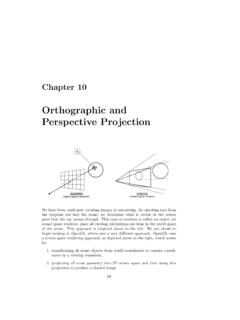
4 Some systems use separate R and W lines, and omit memoryAddress busData bussAddress01232m 1A0 Am 1D0 Db 1R/WREQUESTCOMPLETEMDRR egisterfileControl signalsmwwMARb7-7 Chapter 7- Memory System DesignComputer Systems Design and Architecture by V. Heuring and H. Jordan 1997 V. Heuring and H. Jordan: Updated David M. Zar, February, 2001 Table Some Memory PropertiesSymbol Word Size16bits 16bits64 bitsmBits in a logical Memory address 20 bits 20 bits 32 bitssBits in smallest addressable unit 888bData Bus size816642mMemory wd capacity, s-sized wds 2202202322mxs Memory bit capacity220x8220x8232x87-8 Chapter 7- Memory System DesignComputer Systems Design and Architecture by V. Heuring and H. Jordan 1997 V. Heuring and H. Jordan: Updated David M. Zar, February, 2001 Big-Endian and Little-EndianStorageWhen data types having a word size larger than the smallestaddressable unit are stored in Memory the question arises, Is the least significant part of the word stored at thelowest address (little Endian, little end first) or is the most significant part of the word stored at thelowest address (big Endian, big end first) ?
5 Example: The hexadecimal 16-bit number ABCDH, stored at address 0 EndianBig Endian7-9 Chapter 7- Memory System DesignComputer Systems Design and Architecture by V. Heuring and H. Jordan 1997 V. Heuring and H. Jordan: Updated David M. Zar, February, 2001 Table Memory Performance ParametersSymbolDefinitionUnitsMeaningta Access time timeTime to access a Memory wordtcCycle timetimeTime from start of access to start of next accesskBlock sizewordsNumber of words per blockbBandwidthwords/time Word transmission ratetlLatencytimeTime to access first word of a sequenceof wordstbl=Block timeTime to access an entire block of wordstl+ k/baccess time(Information is often stored and moved in blocks at the cache and disk level.)7-10 Chapter 7- Memory System DesignComputer Systems Design and Architecture by V. Heuring and H.
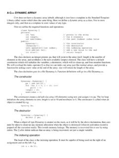
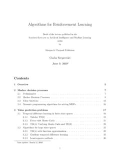
6 Jordan 1997 V. Heuring and H. Jordan: Updated David M. Zar, February, 2001 ComponentAccessRandom Random RandomDirectSequentialCapacity, bytes64-1K4MB4GB85GB1 TBLatency10ns20ns50ns10ms10ms-10sBlock size1 word16 words 16 words4KB4 KBBandwidthSystem 666MB/s 200MB/s160MB/s 4MB/sclockrateCostHigh$50$ $ $ The Memory Hierarchy, Cost, and PerformanceCPUC acheMain MemoryDisk MemoryTapeMemorySome Typical Values:7-11 Chapter 7- Memory System DesignComputer Systems Design and Architecture by V. Heuring and H. Jordan 1997 V. Heuring and H. Jordan: Updated David M. Zar, February, 2001 Intel Architecture Over Time32 KB L1;512 KB L264 GB6432 GP128 M500 MHz10001999 Pentium III32KB L1; 256 KB or 512 KB L264 GB64327 M266 MHz4661997 Pentium II16 KB L1; 256KB or 512 KB L264 M200 MHz4401995 Pentium Pro16 KB L14 M60 MHz1001993 Pentium8 KB L14 M25 MHz201989 Intel486 DXNone4 GB3232275 K20 MHz61985 Intel386 DXNone16 MB1616134 MB161629 K8 in CPU PackageMax, External Address SpaceExternal Data Bus SizeMain CPU Register Size# of Xtorson DieMax.
7 CPU Frequency at IntroductionMIPSR elease DateProcessor7-12 Chapter 7- Memory System DesignComputer Systems Design and Architecture by V. Heuring and H. Jordan 1997 V. Heuring and H. Jordan: Updated David M. Zar, February, 2001 Fig. Memory Cells - a conceptual viewSelectDataInDataOutR/W SelectDataOutDataInR/WRegardless of the technology, all RAM Memory cells must providethese four functions: Select, DataIn, DataOut, and static RAM cell is unrealistic in practice, but it is functionally will discuss more practical designs 7- Memory System DesignComputer Systems Design and Architecture by V. Heuring and H. Jordan 1997 V. Heuring and H. Jordan: Updated David M. Zar, February, 2001 Fig. An 8-bit register as a 1D RAM arrayThe entire register is selected with one select line, and uses one R/W lineData bus is bi-directional, and buffered.
8 (Why?)SelectDataInDataOutR/Wd0 SelectR/Wd1d2d3d4d5d6d7 DDDDDDDDD7-14 Chapter 7- Memory System DesignComputer Systems Design and Architecture by V. Heuring and H. Jordan 1997 V. Heuring and H. Jordan: Updated David M. Zar, February, 2001 Fig. A 4x8 2D Memory Cell ArrayR/W is commonto 8-bit buffered data bus2-4 line decoder selects one of the four 8-bit arraysd0R/Wd1d2d3d4d5d6d7 DDDDDDDDDDDDDDDDDDDDDDDDDDDDDDDD2 4 decoderA1A07-15 Chapter 7- Memory System DesignComputer Systems Design and Architecture by V. Heuring and H. Jordan 1997 V. Heuring and H. Jordan: Updated David M. Zar, February, 2001 Fig. A 64Kx1 bit static RAM (SRAM) chip~square array fits IC designparadigmSelecting rows separatelyfrom columns means only256x2=512 circuit elementsinstead of 65536 circuitelements!CS, Chip Select, allows chips in arrays to be selected individuallyThis chip requires 21 pins including power and ground, and sowill fit in a 22 pin 256 1 mux1 1 256 demux188 Row address:A0 A78 256rowdecoder256 256cell arrayColumn address:A8 A15R/WCS7-16 Chapter 7- Memory System DesignComputer Systems Design and Architecture by V.
9 Heuring and H. Jordan 1997 V. Heuring and H. Jordan: Updated David M. Zar, February, 2001 Fig A 16Kx4 SRAM ChipThere is little difference between this chip and the previous one, except that there are 4, 64-1 Multiplexers instead of 1, 256-1 chip requires 24 pins including power and ground, and so will require a 24 pin pkg. Package size and pin count can dominate chip each4 64 1 muxes4 1 64 demuxes486 Row address:A0 A78 256rowdecoder4 64 256cell arraysColumn address:A8 A13R/WCS7-17 Chapter 7- Memory System DesignComputer Systems Design and Architecture by V. Heuring and H. Jordan 1997 V. Heuring and H. Jordan: Updated David M. Zar, February, 2001 Fig Matrix and Tree Decoders 2-level decoders are limited in size because of gate technologies limit fanin to ~8. When decoders must be built with fanin >8, then additional levelsof gates are required.
10 Tree and Matrix decoders are two ways to Design decoders with large fanin:2-4 Decoderx0x1x2x2m0 m4m1 m5m2 m6m3 m72-4 Decoderx0x1x2x3m0m4m8m12m1m5m9m13m2m6m10 m14m3m7m11m153-to-8 line tree decoder constructedfrom 2-input line matrix decoderconstructed from 2-input 7- Memory System DesignComputer Systems Design and Architecture by V. Heuring and H. Jordan 1997 V. Heuring and H. Jordan: Updated David M. Zar, February, 2001 Fig A 6 Transistor static RAM cellThis is a more practicaldesign than the 8-gatedesign shown value is read byprechargingthe bitlines to a value 1/2way between a 0 anda 1, while asserting theword line. This allows thelatch to drive the bit linesto the value stored inthe (from columnaddressdecoder)CSdiSense/write amplifiers sense and amplify dataon Read, drive bi and bi on writeAdditional cellsSwitches to control accessto cell+5 ActiveloadsWord line wiStoragecellDual rail data lines for reading and writing7-19 Chapter 7- Memory System DesignComputer Systems Design and Architecture by V.