Transcription of 7. COOLING TOWER
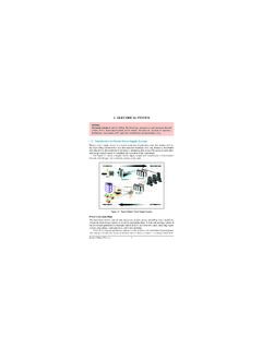
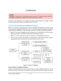
1 7. COOLING TOWER . Syllabus COOLING TOWER : Types and performance evaluation, Efficient system operation, Flow control strategies and energy saving opportunities, Assessment of COOLING towers Introduction COOLING towers are a very important part of many chemical plants. The primary task of a cool- ing TOWER is to reject heat into the atmosphere. They represent a relatively inexpensive and dependable means of removing low-grade heat from COOLING water. The make-up water source is used to replenish water lost to evaporation. Hot water from heat exchangers is sent to the COOLING TOWER .
2 The water exits the COOLING TOWER and is sent back to the exchangers or to other units for further COOLING . Typical closed loop COOLING TOWER system is shown in Figure Figure COOLING Water System COOLING TOWER Types COOLING towers fall into two main categories: Natural draft and Mechanical draft. Natural draft towers use very large concrete chimneys to introduce air through the media. Due to the large size of these towers, they are generally used for water flow rates above 45,000. m3/hr. These types of towers are used only by utility power stations. Mechanical draft towers utilize large fans to force or suck air through circulated water.
3 The water falls downward over fill surfaces, which help increase the contact time between the water and the air - this helps maximise heat transfer between the two. COOLING rates of Mechanical draft towers depend upon their fan diameter and speed of operation. Since, the mechanical draft COOLING towers are much more widely used, the focus is on them in this chapter. Bureau of Energy Efficiency 135. 7. COOLING TOWER Mechanical draft towers Mechanical draft towers are available in the following airflow arrangements: 1. Counter flows induced draft. 2. Counter flow forced draft. 3.
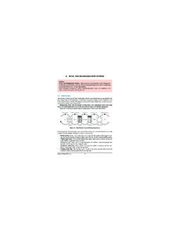
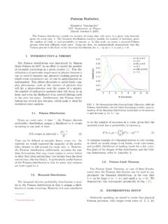
4 Cross flow induced draft. In the counter flow induced draft design, hot water enters at the top, while the air is intro- duced at the bottom and exits at the top. Both forced and induced draft fans are used. In cross flow induced draft towers, the water enters at the top and passes over the fill. The air, however, is introduced at the side either on one side (single-flow TOWER ) or opposite sides (double-flow TOWER ). An induced draft fan draws the air across the wetted fill and expels it through the top of the structure. The Figure illustrates various COOLING TOWER types. Mechanical draft towers are avail- able in a large range of capacities.
5 Normal capacities range from approximately 10 tons, m3/hr flow to several thousand tons and m3/hr. Towers can be either factory built or field erected - for example concrete towers are only field erected. Many towers are constructed so that they can be grouped together to achieve the desired capacity. Thus, many COOLING towers are assemblies of two or more individual COOLING towers or "cells." The number of cells they have, , an eight-cell TOWER , often refers to such towers. Multiple-cell towers can be lineal, square, or round depending upon the shape of the individual cells and whether the air inlets are located on the sides or bottoms of the cells.
6 Components of COOLING TOWER The basic components of an evaporative TOWER are: Frame and casing, fill, cold water basin, drift eliminators, air inlet, louvers, nozzles and fans. Frame and casing: Most towers have structural frames that support the exterior enclosures (casings), motors, fans, and other components. With some smaller designs, such as some glass fiber units, the casing may essentially be the frame. Fill: Most towers employ fills (made of plastic or wood) to facilitate heat transfer by maximis- ing water and air contact. Fill can either be splash or film type. With splash fill, water falls over successive layers of horizontal splash bars , continuously breaking into smaller droplets, while also wetting the fill surface.
7 Plastic splash fill promotes better heat transfer than the wood splash fill. Film fill consists of thin, closely spaced plastic surfaces over which the water spreads, form- ing a thin film in contact with the air. These surfaces may be flat, corrugated, honeycombed, or other patterns. The film type of fill is the more efficient and provides same heat transfer in a smaller volume than the splash fill. Cold water basin: The cold water basin, located at or near the bottom of the TOWER , receives the cooled water that flows down through the TOWER and fill. The basin usually has a sump or low point for the cold water discharge connection.
8 In many TOWER designs, the cold water basin is beneath the entire fill. Bureau of Energy Efficiency 136. 7. COOLING TOWER Figure COOLING TOWER Types In some forced draft counter flow design, however, the water at the bottom of the fill is channeled to a perimeter trough that functions as the cold water basin. Propeller fans are mount- ed beneath the fill to blow the air up through the TOWER . With this design, the TOWER is mounted on legs, providing easy access to the fans and their motors. Bureau of Energy Efficiency 137. 7. COOLING TOWER Drift eliminators: These capture water droplets entrapped in the air stream that otherwise would be lost to the atmosphere.
9 Air inlet: This is the point of entry for the air entering a TOWER . The inlet may take up an entire side of a TOWER cross flow design or be located low on the side or the bottom of counter flow designs. Louvers: Generally, cross-flow towers have inlet louvers. The purpose of louvers is to equal- ize air flow into the fill and retain the water within the TOWER . Many counter flow TOWER designs do not require louvers. Nozzles: These provide the water sprays to wet the fill. Uniform water distribution at the top of the fill is essential to achieve proper wetting of the entire fill surface.
10 Nozzles can either be fixed in place and have either round or square spray patterns or can be part of a rotating assem- bly as found in some circular cross-section towers. Fans: Both axial (propeller type) and centrifugal fans are used in towers. Generally, propeller fans are used in induced draft towers and both propeller and centrifugal fans are found in forced draft towers. Depending upon their size, propeller fans can either be fixed or variable pitch. A fan having non-automatic adjustable pitch blades permits the same fan to be used over a wide range of kW with the fan adjusted to deliver the desired air flow at the lowest power consumption.