Transcription of 7 INTRODUCTION TO PLATE BUCKLING
1 INTRODUCTION TO PLATE BUCKLING 7 INTRODUCTION TO PLATE BUCKLING INTRODUCTION Steel plates are widely used in buildings, bridges, automobiles and ships. Unlike beams and columns, which have lengths longer than the other two dimensions and so are modeled as linear members, steel plates have widths comparable to their lengths and so are modeled as two-dimensional plane members. Just as long slender columns undergo instability in the form of BUCKLING , steel plates under membrane compression also tend to buckle out of their plane. The buckled shape depends on the loading and support conditions in both length and width directions.
2 However, unlike columns, plates continue to carry loads even after BUCKLING in a stable manner. Their post- BUCKLING strengths, especially in the case of slender plates, can thus be substantially greater than the corresponding BUCKLING strengths. This property is of great interest to structural engineers as it can be utilized to their advantage. In this chapter, the expression for the critical BUCKLING strength, of a flat PLATE simply supported on all four sides, is derived. The post- BUCKLING behaviour of plates is described in terms of both stability and strength and compared with the post- BUCKLING behaviour of a column.
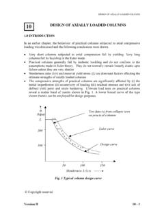
3 The concept of effective width is introduced to tackle the non-uniform distribution of stress in practical plates before and after BUCKLING . BUCKLING of web plates in shear is described and an expression to calculate their ultimate capacity is also given for use in design. A PLATE buckled in shear, can also carry additional shear due to the tension field action. Interaction formulas for plates under various load combinations are also given. CRITICAL STRESS FOR PLATE BUCKLING Rectangular flat PLATE simply supported on four sides Consider a rectangular perfectly flat PLATE simply supported on all four sides and subjected to uniform compressive force Nx per unit length in the x-direction ( ).
4 The equilibrium equation for such a PLATE is given by = + + 22324422444)1(122xwNEtywyxwxwx (1) where, w denotes the deflection in the z-direction of any point (x,y). Copyright reserved Version II 7-1 INTRODUCTION TO PLATE BUCKLING Version II 7-2 y Nxzba ABCD BUCKLING of PLATE under Uni-axial Compression w can be assumed as ===,..3,2,1,..3,2,1sinsinmnmnbynaxmww (2) The m and n in Eq. 2, indicate the number of half sine waves in the buckled mode. It may be noted that this assumed shape automatically satisfies the hinged boundary conditions for the PLATE , that is w = 0 at x = 0, x = a, y = 0 and y = b.
5 Substitution of Eq. (2) in Eq. (1) gives (3) 2223244422422444)()1(122amNEtbnbanmamcrx = ++ Therefore, ()2222322222222232)1(12///)1(12)( + =+ =mbanamEtambnamEtNcrx (4) The lowest value of the membrane BUCKLING stress (Nx)cr, in Eq. (4) is obtained for n=1 and can also be written as follows, ()222321)1(12 + =bamabmbEtNcrx (5) INTRODUCTION TO PLATE BUCKLING Denoting the quantity within larger brackets by k and noting that the BUCKLING load, Ncr, is the product of the BUCKLING stress cr and the thickness, we get the BUCKLING stress as 222)/)(1(12tbEkcr =(6) The expression for the critical BUCKLING stress is similar to the Euler stress for columns [ e= 2E/( /r)2 ] except for the fact that it is a function of the width-thickness ratio b/t.
6 Why should the critical BUCKLING stress in the x-direction be a function of the width b in the y-direction? As the compressive load Nx on the PLATE is increased and reaches the critical BUCKLING load Ncr, the central part of the PLATE such as the strip AB tends to buckle. Now, if we consider a transverse strip CD, we can realize that this strip resists the tendency of the strip AB to deflect out of the plane of the PLATE (z-direction). The shorter the width b, more will be the resistance offered by CD to AB. Hence the strip AB until BUCKLING behaves like a column on elastic foundation, whose stiffness depends on b.
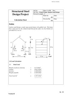
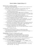
7 This is the reason why the width b figures in the expression for critical BUCKLING stress. Next, let us consider the influence of the length a of the PLATE on the BUCKLING shape. Equation (5) is plotted in Fig. 3, showing the variation of BUCKLING strength with respect to b/a ratio and for various values of m. Consider a PLATE whose length a is much greater than the width b. If a longitudinal strip such as AB in Fig. 1, tends to form a single buckle, its curvature will be much less than the curvature of the transverse strip CD which tries to resist the BUCKLING . This means that the resistance is greater than the tendency to buckle and the strength corresponding to this mode (m=1) is very high.
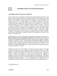
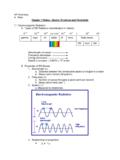
8 Therefore, the PLATE prefers to buckle such that the curvatures of longitudinal and transverse strips are as equal as possible. This leads to multiple buckles in alternate directions as shown in such that the buckles are as square as possible. If a = 2b, the PLATE develops two buckles, if a = 3b, it develops three buckles and so on (Fig. 2). a = 3b b a = 2bb Fig. 2 BUCKLING Modes for Long PlatesVersion II 7-3 INTRODUCTION TO PLATE BUCKLING Variation of k, the PLATE BUCKLING coefficient, with aspect ratio (the ratio of the length, a, to the width, b) is shown in Fig. 3 for m=1,2,3, etc.
9 It can be seen that the lowest value of the BUCKLING coefficient is obtained for integral values of the aspect ratio. Correspondingly square half waves are the BUCKLING mode shapes. Usually the plates are long in practice and for large aspect ratios the BUCKLING coefficient is almost independent of the aspect ratio and is equal to the lowest value of Hence the local BUCKLING coefficient is taken to be the smallest value, independent of the aspect ratio and equals for the case discussed. a/b k m= 3 m = 2 m = 1 Fig. 3 k-values for a Simply Supported PLATE Plates with Other support Conditions So far, it has been assumed that the PLATE is free to rotate about the longitudinal edges.
10 Other edge conditions are of course possible. Consider for example, a box column made up of four plates as shown in Fig. 4 (a). If the flanges are relatively stiff, they would prevent the rotation of the corners [Fig. 4 (b)] and the web PLATE will behave as if its longitudinal edges are fixed. In this case, the bending resistance offered by the transverse strips such as CD will be considerably more than that of a PLATE with simply supported longitudinal edges and the BUCKLING stress will be larger. If the flanges are also prone to BUCKLING , then the corners will rotate as shown in Fig. 4c and the critical BUCKLING stress will be the same as that for a PLATE with simply supported longitudinal edges.