Transcription of Structural Steel Rev Design Project
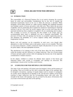
1 portal frames Version II 36 - 1915 m 30 m 5 m c / c 3 m 6 m m 15 m m m A B C D E F G Job No: Sheet 1 of 30 Rev Job Title: Portal frame Analysis and Design Worked Example: 1 Made By PU Date Structural Steel Design Project Calculation Sheet Checked By VK Date Problem Analyse and Design a single span portal frame with gabled roof. The frame has a span of 15 m, the column height 6m and the rafter rise 3m. Purlins are provided @ m c/c. Load Load Calculation Dead Load Weight of asbestos sheeting = kN/m2 Fixings = kN/m2 Services = kN/m2 Weight of purlin = kN/m2 --------------- Total load /m2 = kN/m2 --------------- portal frames Version II 36 - m 1 m ( 300 + 60 ) 300 B F m Job No: Sheet 2 of 30 Rev Job Title: Portal frame Analysis and Design Worked Example: 1 Made By PU Date Structural Steel Design Project Calculation Sheet Checked By VK Date Dead load/m run = * 5 = kN / m | kN/m Live Load Angle of rafter = tan-1 (3 ) = From IS: 875 (part 2) 1987.
2 Table 2 (cl ), = kN/m Crane Loading Overhead electric crane capacity = 300 kN Approximate weight of crane girder = 300 kN Weight of crab = 60 kN The extreme position of crane hook is assumed as 1 m from the centre line of rail. The span of crane is approximately taken as m. And the wheel base has been taken as m Vertical load The weight of the crane is shared equally by four wheels on both sides. The reaction on wheel due to the lifted weight and the crab can be obtained by taking moments about the centreline of wheels. MB = 0 ^`5*10)( portal frames Version II 36 - 21 Job No: Sheet 3 of 30 Rev Job Title: Portal frame Analysis and Design Worked Example: 1 Made By PU Date Structural Steel Design Project Calculation Sheet Checked By VK Date 2 RF ( ) = (300 + 60) * 1 + 300 * ( ) RF = 88 kN MF = 0 2 RB ( ) = (300 + 60) * ( ) + 300 * ( ) RB = 242 kN To get maximum wheel load on a frame from gantry girder BB', taking the gantry girder as simply supported.
3 Centre to centre distance between frames is 5 m c/c. Assuming impact @ 25% Maximum wheel Load @ B = (242 (1 + ( )/5) = 375 kN. Minimum wheel Load @ B = (88 /242)*375 = kN Transverse Load: Lateral load per wheel = 5% (300 + 60)/2 = 9 kN ( Lateral load is assumed as 5% of the lifted load and the weight of the trolley acting on each rail). Lateral load on each column *3752429 = kN (By proportion) 242 kN 242 kN m 5 m B' B portal frames Version II 36 - 22 Job No: Sheet 4 of 30 Rev Job Title: Portal frame Analysis and Design Worked Example: 1 Made By PU Date Structural Steel Design Project Calculation Sheet Checked By VK Date Wind Load Design wind speed, Vz = k1 k2 k3 Vb From Table 1; IS: 875 (part 3) 1987 k1 = (risk coefficient assuming 50 years of Design life) From Table 2.)
4 IS: 875 (part 3) 1987 k2 = (assuming terrain category 4) k3 = (topography factor) Assuming the building is situated in Chennai, the basic wind speed is 50 m /sec Design wind speed, Vz = k1 k2 k3 Vb Vz = 1 * *1 * 50 Vz = 40 m/sec Basic Design wind pressure, Pd = *Vz2 = * (40)2 = kN/m2 Wind Load on individual surfaces The wind load, WL acting normal to the individual surfaces is given by WL = (Cpe Cpi ) A*Pd (a) Internal pressure coefficient Assuming buildings with low degree of permeability Cpi = r portal frames Version II 36 - 23h w w L plan elevation Job No: Sheet 5 of 30 Rev Job Title: Portal frame Analysis and Design Worked Example: 1 Made By PU Date Structural Steel Design Project Calculation Sheet Checked By VK Date (b) External pressure coefficient External pressure coefficient for walls and roofs are tabulated in Table 1 (a) and Table 1(b) Calculation of total wind load (a) For walls h/w = 6/15 = L/w = 30/15 = Exposed area of wall per frame @ 5 m c/c is A = 5 * 6 = 30 m2 For walls, A pd = 30 * = kN Table 1 (a): Total wind load for wall Cpe Cpi Cpe Cpi Total wind(kN) (Cpe-Cpi )Apd Wind Angle T Wind-ward Lee-ward Wind ward Lee ward Wind ward Lee ward 00 900 (b) For roofs Exposed area of each sloping roof per frame @ 5 m c/c is *5A portal frames Version II 36 - 2415 m Job No.
5 Sheet 6 of 30 Rev Job Title: Portal frame Analysis and Design Worked Example: 1 Made By PU Date Structural Steel Design Project Calculation Sheet Checked By VK Date For roof, Apd = kN Table 1 (b): Total wind load for roof Pressure Coefficient Cpe Cpi Total Wind Load(kN) (Cpe Cpi) Apd Cpe Cpe Wind ward Lee ward Wind ward Lee ward Wind angle Wind Lee Cpi Int. Int. 00 900 Equivalent Load Calculation Dead Load Dead Load = kN/m Replacing the distributed dead load on rafter by equivalent concentrated loads at two intermediate points on each rafter, kN615* Superimposed Load Superimposed Load = kN/m Concentrated load , * portal frames Version II 36 - 25 Job No: Sheet 7 of 30 Rev Job Title: Portal frame Analysis and Design Worked Example.
6 1 Made By PU Date Structural Steel Design Project Calculation Sheet Checked By VK Date Crane Load Maximum Vertical Load on columns = 375 kN (acting at an eccentricity of 600 mm from column centreline) Moment on column = 375 * = 225 kNm. Minimum Vertical Load on Column = kN (acting at an eccentricity of 600 mm) Maximum moment = * = 82 kNm Partial Safety Factors Load Factors For dead load, Jf = For major live load, Jf = For minor live load or defined live load, Jf = Material Safety factor Jm = Analysis In this example, the following load combinations are considered, as they are found to be critical. Similar steps can be followed for plastic analysis under other load combinations. (i) + C .L + portal frames Version II 36 - @2w357 Job No: Sheet 8 of 30 Rev Job Title: Portal frame Analysis and Design Worked Example: 1 Made By PU Date Structural Steel Design Project Calculation Sheet Checked By VK Date (ii) + + + + Load and Wind Load (a) Vertical Load w @ intermediate points on windward side w = * *( ) = kN.
7 W @ intermediate points on leeward side w = * * = kN Total vertical load @ the ridge = + = kN b) Horizontal Load H @ intermediate points on windward side H = * sin = kN portal frames Version II 36 - 27 Job No: Sheet 9 of 30 Rev Job Title: Portal frame Analysis and Design Worked Example: 1 Made By PU Date Structural Steel Design Project Calculation Sheet Checked By VK Date H/2 @ eaves points = = kN H @ intermediate purlin points on leeward side = * /3 sin = kN H/2 @ eaves = kN Total horizontal load @ the ridge = - = kN Table 3: Loads acting on rafter points Vertical Load (kN) Horizontal Load (kN) Windward Leeward Windward Leeward Intermediate Points Eaves Ridge Crane Loading Moment @ B = * 225 = kNm Moment @ F = * 82 = kNm Horizontal load @ B & @ F = * = kN Note: To find the total moment @ B and F we have to consider the moment due to the dead load from the weight of the rail and the gantry girder.
8 Let us assume the weight of rail as kN/m and weight of gantry girder as kN/m Dead load on the column = Factored moment @ B & F = * * = kNm * portal frames Version II 36 - 28 Job No: Sheet 10 of 30 Rev Job Title: Portal frame Analysis and Design Worked Example: 1 Made By PU Date Structural Steel Design Project Calculation Sheet Checked By VK Date Total moment @ B = + = kNm @ F = + = kNm + + Dead Load and Live Load @ intermediate points on windward side = * + * = kN @ ridge = kN @ eaves = / 2 | kN. 15 m 3 m 6 m m kN kN kN kN Factored Load ( + + ) kN kN kN kN kN kN kN kN kN kN kN kN kN kN portal frames Version II 36 - 29 Job No: Sheet 11 of 30 Rev Job Title: Portal frame Analysis and Design Worked Example.
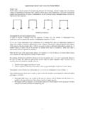
9 1 Made By PU Date Structural Steel Design Project Calculation Sheet Checked By VK Date Crane Load Moment @ B = kNm Horizontal load @ B = kN Moment @ F = kNm Horizontal load @ F = kN Mechanisms We will consider the following mechanisms, namely (i) Beam mechanism (ii) Sway mechanism (iii) Gable mechanism and (iv) Combined mechanism Factored Load ( + + ) 3 m 6 m m kN kN kN kN kN kN 15 m kN kN kNm kNm portal frames Version II 36 - 30 Job No: Sheet 12 of 30 Rev Job Title: Portal frame Analysis and Design Worked Example: 1 Made By PU Date Structural Steel Design Project Calculation Sheet Checked By VK Date Beam Mechanism (1) Member CD Case 1: + + Internal Work done, Wi = MpT + Mp (T/2) + Mp (T + T/2) = Mp(3T) External Work done, We = * - * 1 * T + * * T/2 * 1 * T/2 = Equating internal work done to external work done Wi = We Mp (3T) = Mp = kNm Case 2: + + Internal Work done, Wi = Mp (T +T/2 + T + T/2) Wi = Mp 3T kN kN kN kN kN kN kN kN T/2 T portal frames Version II 36 - 31 Job No: Sheet 13 of 30 Rev Job Title.
10 Portal frame Analysis and Design Worked Example: 1 Made By PU Date Structural Steel Design Project Calculation Sheet Checked By VK Date External work done, We = * T + * = Equating Wi = We, Mp (3T) = T Mp = kNm Note: Member DE beam mechanism will not govern. (2) Member AC Internal Work done, 1311pM 1311 pM pMiW T kN kN kN kN T/2 kN kN T 11T /13 kNm portal frames Version II 36 - 32 Job No: Sheet 14 of 30 Rev Job Title: Portal frame Analysis and Design Worked Example: 1 Made By PU Date Structural Steel Design Project Calculation Sheet Checked By VK Date External Work done, Equating Wi = We, we get MpT = T Mp = kNm.