Transcription of 70-72 Chevelle Installation Manual Rev 091313
1 1970-1972 Chevelle Installation Manual Revised: September 13, 2013 2 TABLE OF CONTENTS Welcome from the Team at Classic Instruments!.. 3 Remove the Original Instrument Cluster from the dash .. 4 Installing your Classic Instruments gauge package .. 6 Wiring Diagram .. 8 Wiring Your New Instrument Cluster .. 9 Speedometer Wiring with SN16 Signal .. 9 Speedometer Wiring with SN74 Signal Interface .. 10 Tachometer / Quad Gauge Wiring .. 13 Calibrate the Speedometer .. 16 SN16 Signal Calibration .. 16 16,000 PPM Speedometer Calibration Chart .. 17 SN74 Speedometer Signal Interface Calibration .. 18 Revised: September 13, 2013 3 Welcome from the Team at Classic Instruments! Our congratulations and appreciation for your purchase of one of the finest quality sets of specialty instruments ever produced! Your instrument set has been conceived, designed, and manufactured by Classic Instruments, Inc.
2 In the Each instrument has been tested and certified for accuracy and quality before packaging and shipping. For trouble-free Installation and operation follow the instructions exactly as outlined. Your instruments were assembled to precise specifications and although each has a five (5) year warranty covering defective parts and workmanship this warranty will not cover instruments or sender units which have been installed incorrectly. Follow our recommended procedures for Installation and proper hookup to maintain the value and appearance of your instrument set during many future years of accurate and dependable service! LIMITED WARRANTY Classic Instruments, Inc. (CI) warrants to the original purchaser that any CI product manufactured or supplied by CI will be free from defects in material and workmanship under normal use and service for a period of five (5) years from date of purchase. Improper Installation , use of sending units other than CI s or attempted repair or adjustments by other than CI shall void this warranty.
3 Disassembly of any instruments or senders for whatever reason shall specifically void this warranty. It s always easy to look to a part for an issue with your set. Before you conclude that a part may be bad, thoroughly check your work. Today s semiconductors and passive components have reached incredibly high reliability levels, but there is still room for error in our human construction skills. However, on rare occasions a sour part can slip through. Please be aware that testing can usually determine if the part was truly defective or damaged by assembly or usage. Don t be afraid of telling us that you blew it , we re all human and in most cases, replacement parts are very reasonably priced. Purchaser requesting a product to be repaired or replaced under warranty must first call CI at 1-800-575-0461 before the return of defective part. Send defective part either to 826 Moll Drive, through UPS, or to Box 411 through Mail, Boyne City, MI 49712, USA.
4 Include a written description of the failure with defective part. Purchaser agrees and accepts that under no circumstances will a warranty replacement be furnished until CI has first received, inspected, and tested the returned part. All other warranties expressed or implied are hereby excluded including any implied warranty of merchandise and implied warranty of fitness for a particular purpose. The sole and exclusive remedy for breach of this warranty is limited to the replacement set forth above. It is expressly agreed that there shall be no further remedy for consequential or other type of damage, including any claim for loss of profit, engine damage or injury. TECHNICAL ASSISTANCE 1-800-575-0461 OR Visit our website for the latest in gauge design and updates to our Installation Manual Revised: September 13, 2013 4 Remove the Original Instrument Cluster from the dash 1) Remove the dash pad. 2) Remove the four screws fastening the lower steering column trim piece with a Phillips screwdriver.
5 3) Remove the two nuts that hold the steering column in place. 4) Lower the steering column. Take note if any shims are on the column mount. a. NOTE: If the car is column shift the shift indicator cable will need to be removed from the right hand side of the column. Care must be taken not to break it. 5) Remove the four heater control panel screws and move the heater control panel out of the way. 6) Remove any speaker brackets that prevent the dash from being removed. 7) Remove the seven bolts/screws that hold the dash panel assembly in the car with a 7/16 wrench/socket/swivel-socket. Save the bolts/screws and take note of their locations. 8) Pull the dash panel forward and remove the speedometer cable from the speedometer assembly. Fastener LocationsRevised: September 13, 2013 59) Carefully disconnect any wire connections from the dash panel and components mounted in the dash panel or that are preventing the dash panel from being removed.
6 See the below list as a guideline for connections to be removed: a. Cigarette lighter b. Blower motor c. Stereo d. dash lights e. Glove box light f. Radio antenna g. Headlight switch 10) Remove the dash panel from the vehicle. 11) Remove the headlight switch. 12) Remove the original dash carrier with the seven mounting screws. 13) Remove the instrument panel lens. Take care not to scratch the lens if you are reusing it. 14) Remove the speedometer cable from the vehicle. Mounting Screw Locations Revised: September 13, 2013 6 Rubber bumper Installing your Classic Instruments gauge package 1) Clean your original lens with a soft rag and cleaner if it is being reused. 2) Pull the supplied rubber bumper through the front side of the clock reset hole in the lens to seal the lens. Cut the excess length off the backside of the bumper. If the original lens is being reused and the hole already has a plastic plug, the included rubber bumper is not needed.
7 3) Carefully use compressed air to blow any dust off the gauge faces or out of the gauge carrier. 4) Place the lens on the dash carrier lining up the locating pins. Make sure the lens is completely seated on the carrier. 5) Place the headlight switch lens on the dash carrier using the three locating pins and slot. Two different colors of lens (white and green) are supplied; either can be used based on your personal preference. Revised: September 13, 2013 76) Install the gauge package into the dash with the supplied #8 high-low thread screws and a #2 Phillips screwdriver. 7) Reinstall the headlight switch. 8) Reinstall the dash panel into the vehicle. 9) Reconnect any wire connections that were disconnected to remove the dash from the vehicle. 10) Reinstall the speaker mounts and speakers. 11) Reinstall the heater control panel. 12) Reinstall the steering column with the original shims (if required) and two mounting nuts.
8 13) Reinstall the lower steering column trim piece with the Phillips-head screws. 14) Use the wiring diagram and information below to make the necessary wiring connections. Secure the wiring harness under the dash . 15) Calibrate the speedometer using the instructions starting on page 15. Classic Instruments recommends using the SkyDrive GPS speedometer sending unit (SN81) or Speedometer Signal Interface (SN74) to make the speedometer calibration easier. These parts will eliminate the need for the dip switches on the back of the speedometer housing which are difficult to access once the dash panel/instrument cluster are installed. If you choose to use the dip switch method of calibration the dash panel may need to be removed to access the back of the speedometer. 16) Reinstall the dash pad. #8 High-Low Screws Revised: September 13, 2013 8 Wiring Diagram OPEN123456789101112 SIGGNDB+A1234123457682134 UNSWSWLT+12 VGNDSIG+12 VDC Switched [Pink - A]Good Chassis Ground [Black - B]Temperature Signal [Dk.]
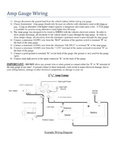
9 Green - C]Tachometer Signal [White - D]Fuel Level Signal [Tan - E]Oil Pressure Signal [Dk. Blue - F]ABCDR ight Turn Indicator [Blue - A]Left Turn Indicator [Lt. Blue - B]High Beam Indicator [Lt. Green - C] dash Lights [Grey - D]PinkWhiteBlackGreyLt. GreenBlueGreyLt. BlueGreyDk. BlueBlackPinkTanDk. GreenSpeed Sensor Ground [Yellow - A]Speed Signal [Purple - B]Speed Sensor Power [Purple / White - C]Spare [D]Dedicated Chassis Ground [Black / White - E]+12 VDC Switched / Dedicated [Pink / White - F]ABCDEFP urplePink / WhitePurple / WhiteBlack / WhiteYellowTachometer /Quad HarnessSpeedometerHarnessLighting HarnessABCDEF Revised: September 13, 2013 9 Wiring Your New Instrument Cluster Speedometer Wiring with SN16 Signal 1) Always disconnect the positive lead from the vehicle battery before wiring any gauge. 2) Connect the yellow wire (position A) of the speedometer wire harness to the black wire of the SN16 pulse signal generator.
10 3) Connect the purple wire (position B) of the speedometer wire harness to the white wire of the SN16 pulse signal generator. 4) Connect the purple / white wire (position C) of the speedometer wire harness to the red wire of the SN16 pulse signal generator. 5) Connect the black / white wire (position E) of the speedometer wire harness to a dedicated chassis ground that is not contacting any other ground wires. 6) Connect the pink / white wire (position F) of the speedometer wire harness to a dedicated switched +12 VDC power source. RedBlackWhite Red: +12 VDC (to purple / white wire of speedometer harness) Black: Ground (to yellow wire of speedometer harness) White:Signal (to purple wire of speedometer harness) Revised: September 13, 2013 10 Speedometer Wiring with SN74 Signal Interface 1) Always disconnect the positive lead from the vehicle battery before wiring any gauge.