Example: bankruptcy
1967-1972 Chevy Truck Installation Manual
Jun 18, 2002 · connection for the sender ground. 4) Connect a wire from the top terminal of the oil pressure sender to the Blue wire of the gauge wire harness. Temperature Sender Installation (Part No. SN22, SN23, SN24 & SN25) 1) Disconnect battery before making any connections. 2) Install the Classic Instrument’s temperature sending
Tags:
Information
Domain:
Source:
Link to this page:
Documents from same domain
1967-1968 Camaro - Classic Instruments
www.classicinstruments.comInstall the Classic Instruments oil pressure sender in the engine block. GM engine installations require the use of the 2-piece brass bushing kit which includes a 45 degree elbow ... The fuel level gauge in your instrument cluster is designed to work with the stock fuel sending unit in your 1967 – 1968 : : : : : :

1957 Chevy Installation Manual Revision 010615
www.classicinstruments.comJun 15, 2001 · For all other ignition systems please look at the owner’s manual for that system. 7) Connect the oil pressure sender to the BLUE wire of the gauge cluster wire harness. 8) Connect high beam indicator power to the GREEN wire of the gauge cluster wire harness. 9) Connect dash light power to the GREY wire of the gauge cluster wire harness.
70-72 Chevelle Installation Manual Rev 091313
www.classicinstruments.comcomponents mounted in the dash panel or that are preventing the dash panel from being removed. See the below list as a guideline for connections to be removed: a. Cigarette lighter b. Blower motor c. Stereo d. Dash lights e. Glove box light f. Radio antenna g. Headlight switch 10) Remove the dash panel from the vehicle. 11) Remove the headlight ...
Amp Gauge Wiring - Classic Instruments
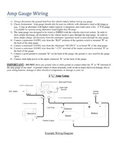
www.classicinstruments.comAmp Gauge Wiring 1) Always disconnect the ground lead from the vehicle battery before wiring any gauge. 2) Classic Instruments’ Amp gauge should only be used on vehicles with alternators rated at 60 Amps or less. Using an alternator with higher output capacity is dangerous and could cause a fire. A Volt gauge
Related documents
Fuel Level Sender Installation Instructions
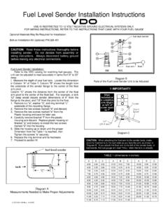
www.vdo-gauges.comFuel Level Sender Installation: Refer to the VDO catalog for matching fuel gauges. The unit can be adjusted to read accurately in tanks from 6" to 23" deep. Diagram B I. Measure the depth of your fuel tank. Locate this dimension in Column "A" of Table 1. Column "B" shows the length from the underside of the sender flange to the center of the float

FUEL LEVEL GAUGE INSTALLATION INSTRUCTIONS
images.carid.com5. read the fuel level tank sender instructions and install the sender. 6.RefertoFigure 3. Route a length of 18-gauge insulated copper wire from the gauge to the sender. connect the wire to the sender. onnect the other end of the wire to the connection post on the back of the gauge marked “S”. 7.Make sure the fuel level sender is grounded to

GM LS Engine Gauges Installation Guide - Autometer
www.autometer.com#2277 adapter, and a #2259 sender (both included in the LS Installation kit). The #2259 sender is necessary since the probe of the #2258 (normally included sender with your gauge kit) will NOT go through the adapter. The #2259 is a probe-less sender, using the same resistance range as the #2258. Do not attempt to drill out the 2277 to accept ...

GSS-3000 Universal Gear Shift Sender Your new GSS-3000 ...
www.dakotadigital.comInstallation: GM Applications TH350, TH400, 700R4, and 4L60E/4L70E Connecting rod length for GM applications is typically 4.25” from rod end eye to eye. GM 700R4 installation, top view *4L60/70E - use 700R4 mounting holes with sensor facing out* GM TH350 installation, top view GM 4L60 installation, top view GM TH400 installation, top view
1967-1968 Camaro - Classic Instruments
www.classicinstruments.comInstall the Classic Instruments oil pressure sender in the engine block. GM engine installations require the use of the 2-piece brass bushing kit which includes a 45 degree elbow and 1 inch extension. The threads of the sender and bushing kit are tapered and should not require additional sealant. Do not use Teflon tape on the threads of any part of
Wire Harness Installation Instructions - Painless Performance
www.painlessperformance.comIncludes dome lights (see Paragraph 10.4.2), left and right turn signals, brake lights, and fuel sender. Installation requires four (4) easy steps: 1. Connect to the fuse block 2. Route the wires 3. Cut off the excess wire 4. Terminate the wires
Wire Harness Installation Instructions - Painless Performance
www.painlessperformance.comIncludes tail lights, dome lights (see Paragraph 10.4.2), left and right turn signals, brake lights, and fuel sender. Installation requires four (4) easy steps: 1. Mount the fuse block
INSTALLATION INSTRUCTIONS ELECTRIC SPEEDOMETER
www.autometer.comThe speed sender signal range must be between 500 and 400,000 pulses/mile (310 and 248,500 pulses/km). Any speed sender or electronic module that meets the following two conditions can be used: 1. Pulse rate generated is proportional to vehicle speed. 2. Output voltage within the ranges listed below: • Hall effect sender, 3-wire (5 to 16V)