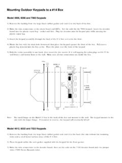
Transcription of 7000 Series Keypad - CORBY KEYPADS & CORBY ACCESS …
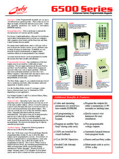
1 DESCRIPTIONSET THE CODE LENGTHSELECTING A CODERELAYS/RELAY MODULESSECONDARY CODES USING TWO-DIGIT CODES 7000 Series KEYPADS provide a momentary voltage output when the user-programmed 4 or 5 digit code is entered. Use this output to arm/disarm alarm systems, trip panic zones, activate a relay to control door locks, shunt bypasses, or operate garage door openers. Eight two digits codes are also H1 selects a five or four digit code. The Keypad is shipped with a jumper in the "C" and "5" position on this header, which sets the Keypad for a 5 digit ) Remove the circuit board2) Locate the Header (H1)3) Remove the small black jumper 4) Re-install the jumper on "C" and "4"H1 must be installed for Keypad ) Locate the five colored programming code wires packed in the plastic parts bag with the mounting hardware. 2) Locate the code bank on the circuit board. It has 17 socket positions which are printed on the circuit ) Sockets A B C D E represent the five possible digits of the code.
2 Socket A is the first digit, B the second, C the third, D the fourth, and E the ) Program the first digit of the code by placing one end of a code wire in the A position and the other end in the desired digit. Repeat the process for the remainder of the selected digits. Digits can only be used for the code 14735:A to 1 B to 4 C to 7 D to 3 E to 5 If selecting a four digit code, "E" is not ) Attach the circuit board. Align socket "S2" with the 13 pins on the Keypad and carefully press the socket onto the pins. (+) positive 6-24 VDC supply voltage input. This voltage should be filtered, regulated, uninterrupted and able to supply a minimum of 50mA for the Keypad , and 20mA for LED or nite-lite. (-) negative VDC supply voltage the chart on the back page. If your panel is not listed, find the arm/disarm terminals marked "keyswitch". One terminal is the arm/disarm terminal and, in most cases, the other is constant positive or negative voltage.
3 Connect the wire for positive voltage. C onnect the wire for negative voltage. Wire multiple KEYPADS in parallel by connecting LEDs and outputs back to the control panel. The wire is negative (-). The other wire on the LED is positive (+).If the other wire is it is rated 12 VDC, 6 VDC or 24 VDC. When the correct code is entered, the Blue wire switches to a positive level or the Green wire switches to a negative level. The voltage will remain present as long as the last digit of the code is depressed. These are transistor outputs not relay contacts. CORBY supplies a variety of relays, listed below, to fit most 86: Used for a single zone shunt, activating a door lock, or operating a garage door opener with an LED 74: Controls two independent latching shunts with an LED 78: Used to trip a dialer or zone. Model 25: (6 or 12 VDC) momentary relay Model 22: (12 VDC) latching (on/off) relay .Touching two buttons simultaneously can give you up to eight - two digit codes to activate a CORBY relay (models 74, 78 or 86).
4 The two digit codes can trip a dialer for panic, shunt a zone, activate a door lock, first digit of the main code is always the first digit of all the two-digit codes. The second digit is selectable and can be any unused digit on the Keypad . The Keypad and any module must share a common ground connection. The two digit codes trigger any other device other than those select a four digit code:RedeachBlackBlueGreenDO NOT CONNECT BOTH WIRES!LED CONNECTIONS:YellowRedGreenBlackUse the following relay modules if dry circuit relay contacts are required: For the main output only:CANNOT WIRE CONNECTIONSMAIN CODE OPERATION1) Insert the Brown diode code wire (included with the mounting hardware) in the Code Bank socket position that corresponds with the second control ) Connect the stranded end of the wire to the positive (+) trigger of the 86, 78 or ) Touching the first button of the main code and the second control button simultaneously will trigger the ) Insert the Brown diode code wire #70 (included with the mounting hardware) in the selected Code Bank ) Connect the stranded en d of the wire to any positive input terminal of your alarm control or digital dialer that is active 24 hours a day.
5 The trigger is 1mA at 12 VDC. 3) If momentary relay contacts are required, connect the stranded end of the program wire to the positive trigger input of a CORBY Model 78 low-level relay Industries, Inc. and/or the seller's only obligation shall be to replace such quantity of the product proved to be defective. Neither the seller nor CORBY shall be liable for any in jury, loss, or damage arising out of the use or the inability to use this product, including the warranty of merchantability or fitness for normal use. Before using, the user shall determine the suitability of the product for his intended use. The user assumes all risk and liability whatsoever in connection therewith. The foregoing may not be altered except by an agreement signed by the officers of the seller and those of CORBY Industries, Inc. 6-24 Volts DC Only (+) or (-) Voltage Driver 30 0mA MAX -18C to 55C (0F to 131F)Single " X "(53 X 40mm)Double " X "(115 X 114mm)Heavy " X "(84 X 127mm)Lock " X "(120 X 133mm) VoltageIdleOperating 6V4mA 14mA 12V8mA 30mA 24V21mA 70mAFor Panic operation:Input Voltage:Outputs:Operating Temp:Dimensions:Power Consumption:LIMITED WARRANTYSPECIFICATIONS 7000 Series KeypadLEDSA cronAlarm ControlsAlarm ControlsAlarm ControlsAdemcoAdemcoAritechCaddiDTIDTIFB IFBIFBIFBIFBIFBIF ranklinGuardwareGuardwareMicro StateMicro StateMicro StateMooseMooseMooseNAPCONAPCONAPCONAPCO R adionicsRadionicsSecurtecSecurtecSescoaS ilent KnightSurgardSurgardSurgardUSPUSPUSP5555 5555555565544555555555555454455555555No.
6 Of WiresRequired111211116B52615151625712251 625(+)29622551571592631336624B3B3B369510 8201619A201161615242010141526(-)11343374 164245273272655118B4B4B4142211 NCNCNCNCNCNCNCNC2612 NCNCNCNCNCNC(X3)NCNC448 NCNCNCNCNCNCNCNC231112 NCNCB12B12B6 NCNCNC62222(X3)B4312 NCNC288116624NC365 NCNCNC813(X4)121049(X3)NCNCNC314 NCNCNC5104(X1)(X2)(X2)(X2)(X2)(X2)(X2)5( X2)(X2)(X2)101988 NCEM20(X2)911166146718(X2)2013(X1)NCNC10 25A5A5A1812(X2)9332317A20114161527232128 2123(-)352339231123111136726125118B4B4B4 8127111211116A1751551025714251625RL29655 751571592631625613419A2A2A15695 REDWireBLKWireGRNWireBLUWireNeeds1 WireRED111211114A1841578257122516 NCGL29666751571592631831614220B3B3B3695 REDYEL541419A2011316152622132417NC(-)343 3310241224101227726105518A1A1A147116 REDYELGRNPAS-1 WC612961306131332R/342R4080CS-2006012772 DS51/526421215XL/1213127012721290 AXL1219UL12 BCU-22CU-66630633643 MPI-25 MPI-26 MPI-50 CCI-5BB-5 CCI-7 CCI-830124012/80121295 Auditor 1125202020CC911/CC912SG411/SG411 SMSG911FA4/ZMC6MC7MC4A/MC5 AModelManufacturerPOWERPANEL TYPEARM/DISARMPANICMODEL 7100 CROSS REFERENCE CHARTAdd a Model 86 to convert the momentary output to a timed momentary or latchingrelay output.
7 The 86 also has a built-in LED driver to indicate relay *#REDBLACKBROWNGREENWHITEBLUEYELLOWREDBL ACKBLUEGREENLED WIRE (RED)LED WIRE (YELLOW)FORM CDRY RELAYOUTPUTS12 VDCPOWERSUPPLY( )( )250mAMinimumFORM CDRY RELAYOUTPUTS1234567890*#REDBLACKBLUEGREE NBLACKBLACKBLUERED12 VDCPOWERSUPPLY( )( )250mAMinimumAdd a Model 25 to convert the momentary output to a momentary relay 25 has a built-in diode to reduce electrical noise to the MODEL #25 RELAYS OREQUIVALENTCOIL RESISTANCEMUST BE MORETHAN 100 OHMSWHEN SUPPLYINGYOUR OWN RELAYA 1N4002 DIODEOR EQUIVALENTMUST BE INSTALLEDIN PARALLELACROSS THE COILX1 For panic operation, use a Brown diode code wire #70 (included in the plastic parts bag) to connect a Code Bank Socket to any 24hr loop "input terminal" of the control panel which accepts a positive voltage for activation. Connect the stranded end of the Program Wire to the Panic operation requires the use of a Model 78 Sensitivity Relay Module. Connect a Brown diode code wire #70 between the selected Code Bank Socket and the positive trigger input of the Model 78.
8 Now, use the dry relay contact of the Model 78 to activate the panic circuit of the Use a CORBY Model #25 Model SPDT relay or any other relay with a coil resistance of 100 ohms or more. Connect the black wire of the Model #25 to constant negative (-) and connect the blue wire (+) of the #7100 Decoder Module to the red wire of the #25. Then, connect the normally open contacts of the #25 relay to the keyswitch A 1N4001 diode is required in Series with the blue wire from the Keypad to Terminal #8. The striped side of the diode goes towards the panel.